Profile Lead in/out options
The Lead in and Lead out sections enable you to control the way the tool approaches the profile and retreats away.
None
The tool approaches the milling level and retreats away exactly adjacent to the start point of the profile.
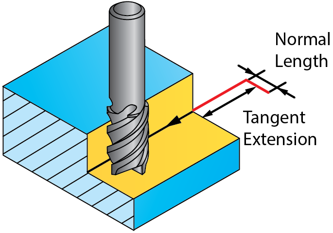
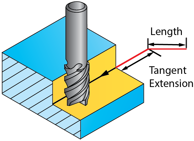
Normal
The tool approaches the profile and retreats away from/to a point normal to the profile. Flip- This option is visible when Tool side is chosen as Center. When this check box is selected, the lead move is flipped to the opposite side from its initial orientation, as if it was mirrored relative to the tool path. The length of the normal can be set in the Length field by entering:
The distance between the normal and material is set in the Tangent extension field. |
 |
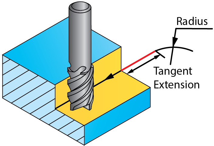
Arc
The tool approaches the profile and retreats away with a tangential arc. Flip- This option is visible when Tool side is chosen as Center. When this check box is selected, the lead move is flipped to the opposite side from its initial orientation, as if it was mirrored relative to the tool path. The arc radius can be set in the Radius field by entering:
The length of the extension can be set in the Tangent extension field. |
 |
Arc angle
This parameter defines the angle of the Lead in arc segment. The default angle value is 90°; in this case, SolidCAM generates a lead in path of quarter arc.
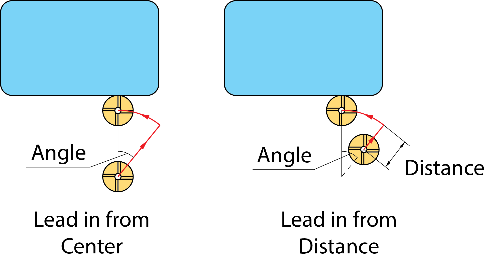
With the Arc Lead in option, the tool moves normal to the lead in arc at the arc start point. The following options are available:
The tool starts milling at the specified distance from the arc start point. When you select Distance the Normal to arc option is enabled by default. Select Tangent to arc option for the tool to start Milling tangentially to the Lead In/Out moves.
The tool starts milling at the lead in arc center.
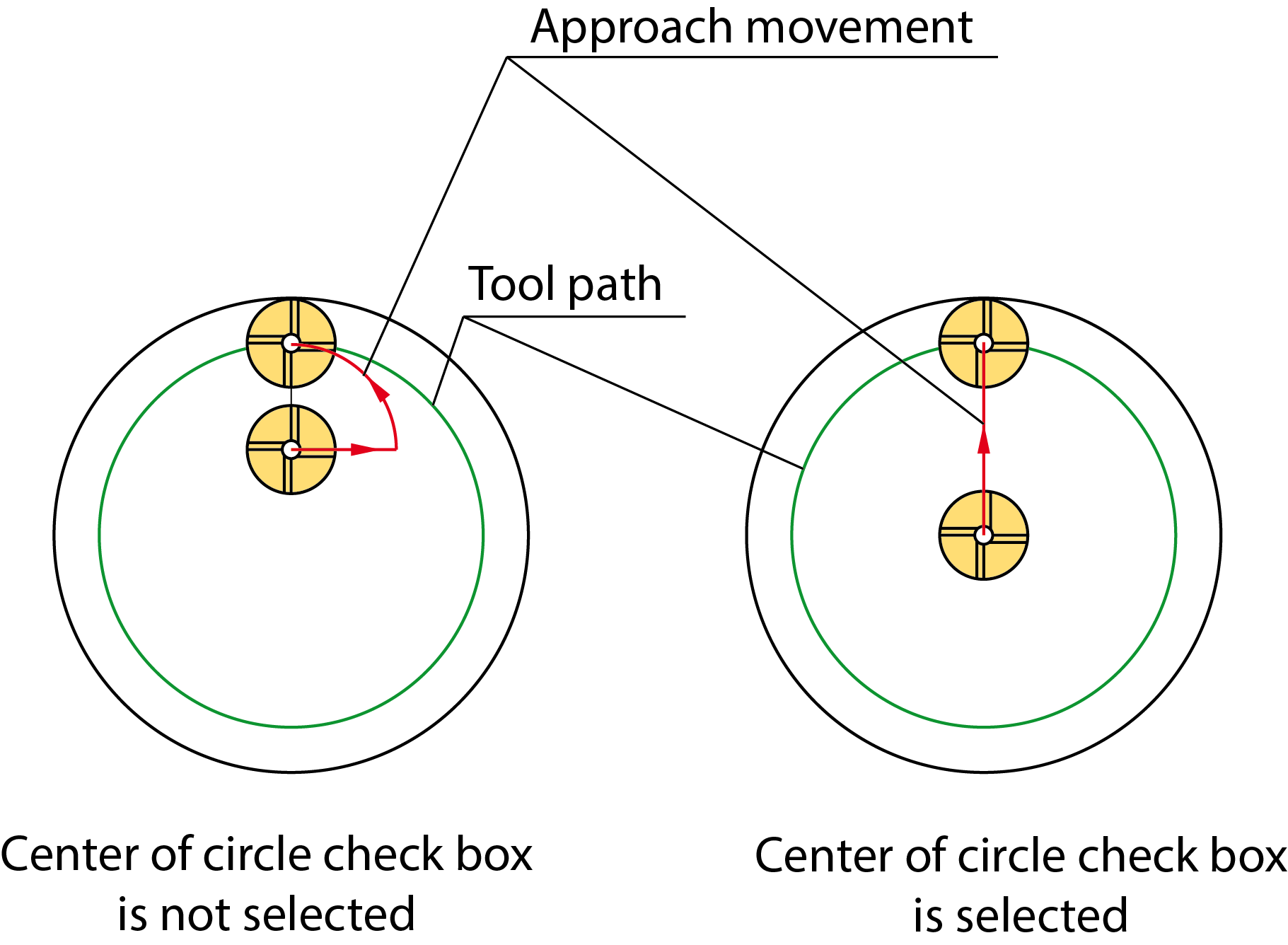
Start from center of circle geometry
When this check box is not selected, the tool rapidly moves from the Clearance level to the Safety distance, enters the material in the center of the defined approach arc and performs the arc movement to the geometry start point at the first cutting level.
When this check box is selected, the tool rapidly moves from the Clearance level to the Safety distance, enters the material in the center of the profile geometry and performs a linear movement to the geometry start point at the first cutting level.
End at center of circle geometry
When this check box is not selected, the tool performs the arc movement from the geometry end point and is removed at the center of the defined retreat arc.
When this check box is selected, the tool performs a linear movement from the geometry end point and is removed at the center of the profile geometry.
Tangent
The tool approaches the profile and retreats away on a line tangent to the profile. The length of the tangent line can be set in the Length field by entering:
The distance to the material can be set in the Tangent extension field. |
 |
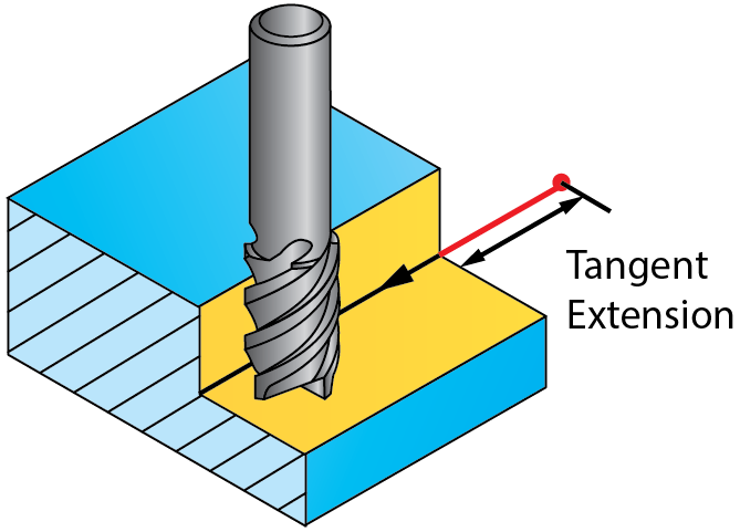
Point
The tool approaches the profile
and retreats away from/to a user-defined position. From this position,
the tool performs a linear movement to the start point of the
profile. When you choose this option, Pick
is activated and you can select a position directly on the solid
model. You can extend the geometry by the value set in the Tangent extension field.
|
 |
User-defined
The tool leads in/out from a user-defined position. When you select this option, you can define a geometry of the tool approach to the material. Click Define to open the Geometry Edit dialog box. You can view the defined geometry by clicking Show.
Same as Lead in
When this check box is selected, the strategy and parameters defined for Lead in are used for Lead out.
|
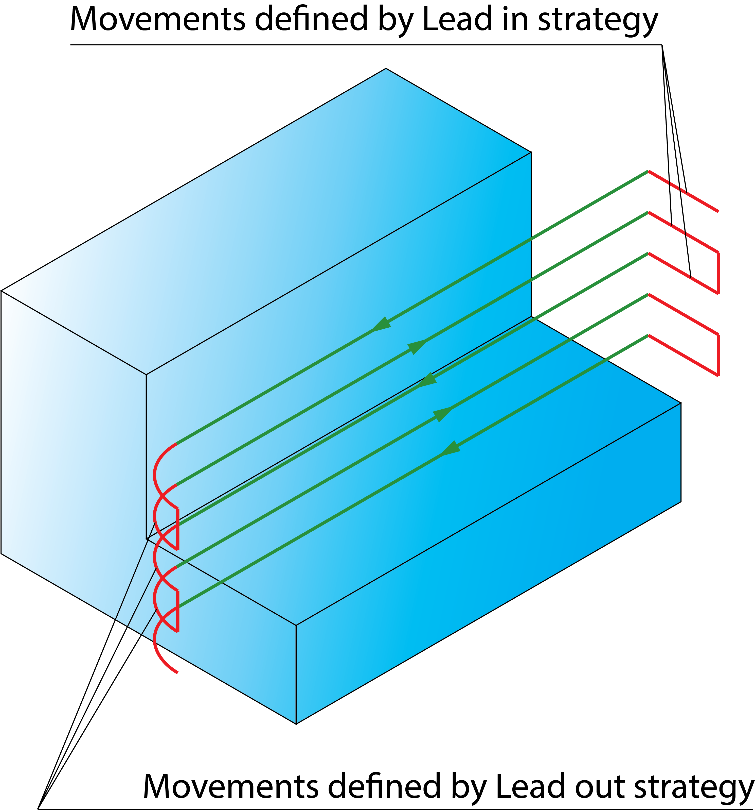
When the Zigzag option is used, the lead in/out movements for all the cuts are calculated according to the direction of the first cutting pass, irrespective of the direction of the other cutting passes. During the tool path linking, SolidCAM connects the cuts that contain lead in and lead out movements in a zigzag manner and changes the direction of all even cuts to the opposite. Therefore only for odd cuts, the Lead in strategy is used for approaching and the Lead out strategy is used for retreating. For even cuts, the Lead in strategy is used for retreating and the Lead out strategy is used for approaching.
|
Related Topics