Stock model definition
The Stock model option enables you to define the actual material that has to be removed.
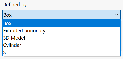
Stock definition modes (Defined by)
This section enables you to define the Stock model by the following methods:
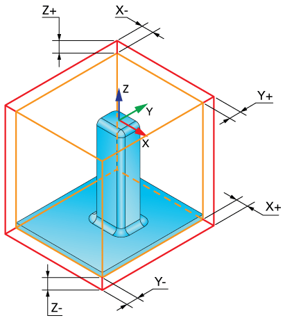
This option enables you to define the Stock boundary as a box surrounding the selected solid model. When you click on the solid body, SolidCAM generates a 3D box around it. This box defines the geometry of the Stock.
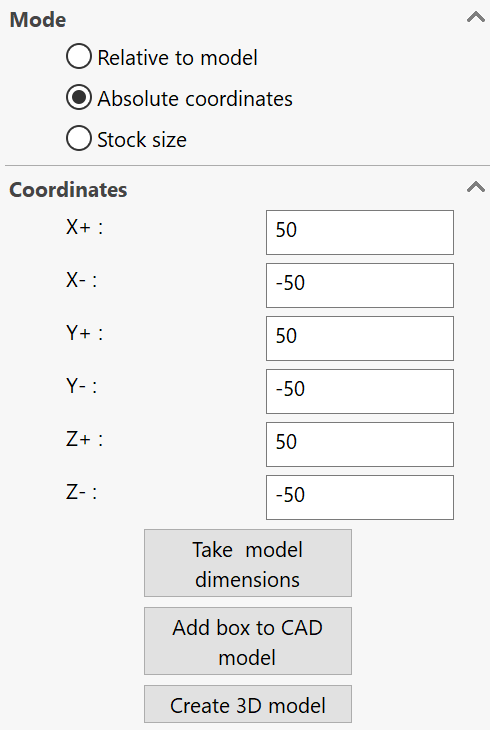
The Expand box at section enables you to define the stock by specifying offsets of the box faces from the selected solid body or coordinates of the box boundaries relative to the CAM-Part Coordinate System.
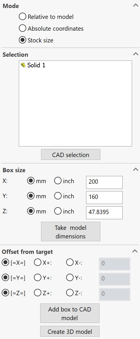
Add box to CAD model- This option enables you to add the stock model box to the CAD model.
Create 3D model- This option enables you to create a 3D model of your stock in addition to adding a box to CAD Model.
Relative to model
When the Relative to model option is chosen for Mode, the box is defined by offsets from the solid model faces.
The Expand box at section enables you to define the stock by specifying offsets of the box faces from the selected solid body in every direction.
|
The box defined by absolute values is not associative to the solid model. |
|
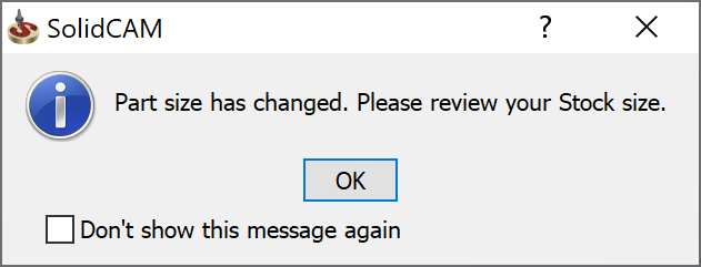
1. After defining the stock in the Stock size Mode if you modify the Box size, and check the synchonization by right-clicking Stock and selecting Synchronize the following message is displayed:
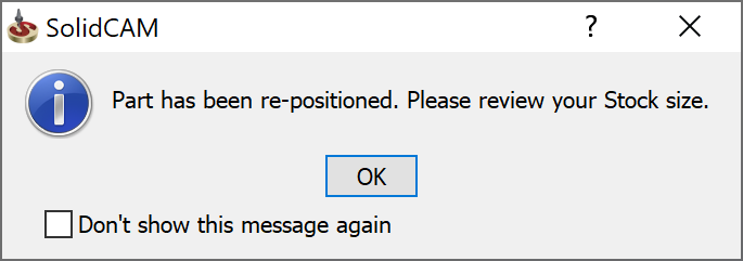
2. After defining the MAC 1 Position 1 in the CoordSys Manager if you change the MAC 1 Position 1, the following message is displayed.
The "Don't show this message again" check box enables you to avoid displaying the message after it appears on the screen for the first time. You can permanently disable this pop-up window by clearing the check box for this message in CAM messages. When the check box is cleared, the message is not displayed, and confirmation of the event is performed automatically.
|
High precision (faceting)
When this check box is selected, the box stock is generated through faceting, which results in better visualization of the stock material. With this method, the process of stock generation may take more time to complete.
When this check box is not selected, the box stock is generated using the standard SOLIDWORKS tools.
Facet tolerance
The Facet tolerance parameter defines the accuracy of triangulation of stock and target models, fixture or clamp.
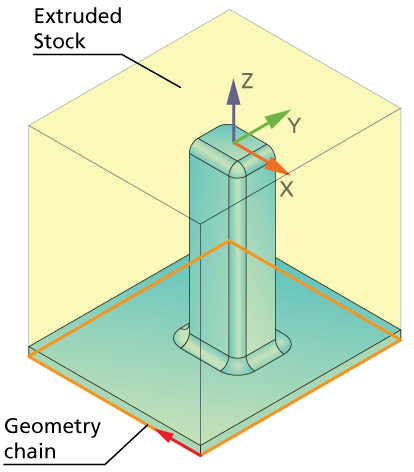
The Stock boundary is defined as a closed wireframe geometry chain using one of the model sketches in the XY-plane. This chain is extruded by the Z-axis to define the Stock model.
|
To extrude the stock at the bottom (Z-level) edit the Part Lower Level parameters in the Planar section of the CoordSys data dialog box. |
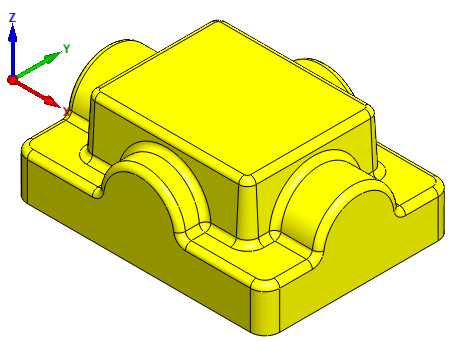
This mode enables you to define the Stock model via 3D model selection, which is useful for casting machining.
The CAD selection button enables you to pick the model with Host CAD tools.
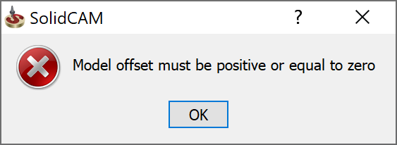
Model Offset
This option offsets the facet model by the value set in this field. The value entered in this field must be positive or equal to zero.
|
If you enter a negative value, the following error message is displayed.
|
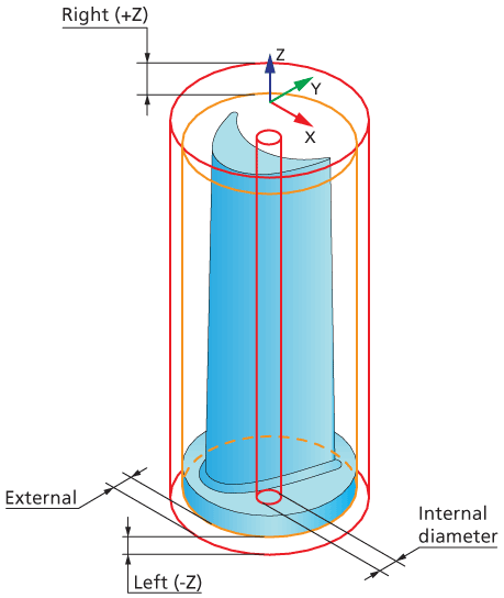
The Stock boundary is defined as a cylinder surrounding the selected solid model. When you click on the solid body, SolidCAM generates a cylinder around it. This cylinder defines the geometry of the Stock.
You can define the cylindrical stock by specifying offsets of the cylinder faces from the selected solid body or coordinates of its boundaries relative to the CAM-Part Coordinate System.
Relative to model
When the Relative to model option is chosen for Mode, the cylinder is defined by offsets from the solid model faces.

The Internal offset is associative to the solid model. A positive value would move it away from the Internal diameter towards '0' and a negative value would move it away from the Internal diameter towards the External Diameter.
|
If the CAM Part is a solid (No Hole) only the Internal diameter is enabled even if you have selected Internal offset in the CAM Part Settings.
|
Absolute coordinates
When the Absolute coordinates option is chosen for Mode, the cylinder is defined by specifying coordinates relative to the CAM-Part Coordinate System. The Coordinates section enables you to define the stock by specifying the cylinder dimensions in Z-coordinate and the values of External and Internal diameters.
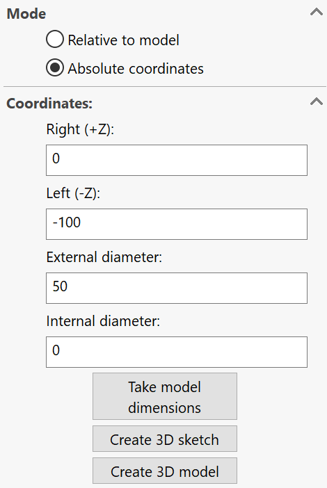
The Take model dimensions button enables you to display the dimensions of the cylinder surrounding the model in the respective coordinates fields.
Create 3D sketch- This option enables you to add a 3D sketch to the CAD model.
Create 3D model- This option enables you to create a 3D model of your stock in addition to adding a cylinder to CAD Model.
|
The cylinder defined by absolute values is not associative to the solid model. |
This mode enables you to define the stock model based on a STL file that exists on your computer. The STL file section enables you to choose the STL file for the stock definition.
The path to the STL file chosen for the stock geometry definition is displayed in this section. The Browse button enables you to display the Browse dialog box from which you can choose the required STL file.