Technology page
Tool side
This option enables you to define the tool position relative to the geometry.
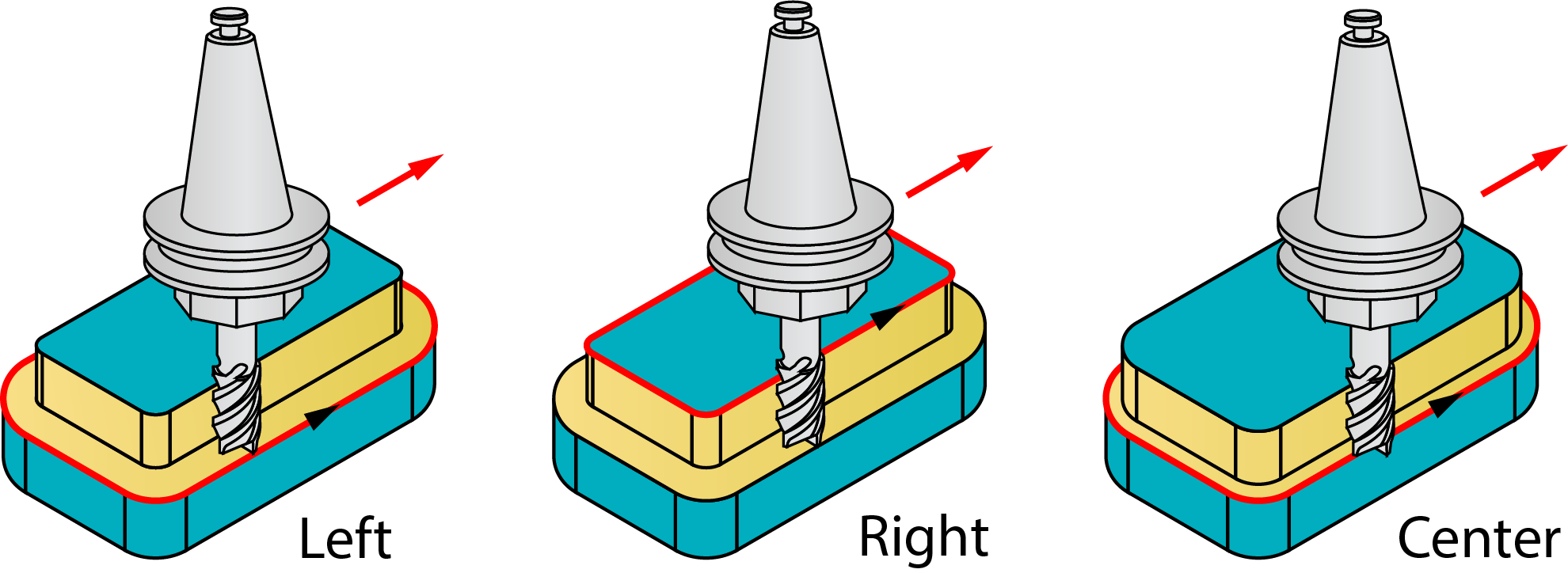
- Right: the tool cuts to the right of the geometry at the distance defined by the values set in Modify offset.
- Left: the tool cuts to the left of the geometry at the distance defined by the values set in Modify offset.
- Center: the center of the tool moves on the geometry. (The compensation cannot be used with this option.)
|
When the Zigzag option is used, the Tool side combo-box defines the tool location for the first cut. For each successive cutting pass, the tool position is changed relative to the geometry direction.
|
Geometry
Clicking this button opens the Modify Geometry dialog box.
Depending on the type of geometry modification, one of the following icons will be displayed next to the Geometry button:
 – indicates that the
geometry has been modified, but no Offset modifications have been
made.
– indicates that the
geometry has been modified, but no Offset modifications have been
made. – indicates that
Offset modifications have been made with positive values only.
– indicates that
Offset modifications have been made with positive values only. – indicates that
Offset modifications have been made with negative values only.
– indicates that
Offset modifications have been made with negative values only. – indicates that
Offset modifications have been made with both positive and negative
values.
– indicates that
Offset modifications have been made with both positive and negative
values.
|
When you hover the mouse pointer over the Offset modification icons, a screen tip displays up to the first ten modified chains and their specified offsets. |
Ignore tool-path intersections with geometry
If the geometry you choose has self-intersections, SolidCAM detects them and displays a warning message. This option enables you to continue machining according to the defined geometry regardless of the self-intersections.
|
By default this option is unchecked. When you select Left /Right Tool side this option is enabled and disabled when center is selected. |
Compensation
If the Compensation check box is selected, the tool radius compensation options G4x of the CNC-controller are used in the GCode.
Rough
This section enables you to perform the rough machining of the slot.
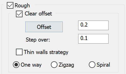
Clear offset
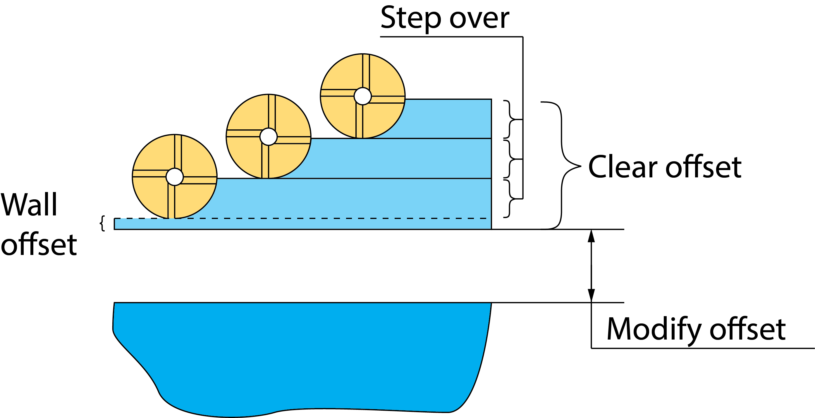
This option generates several concentric profiles with constant depth that start at the defined clear offset distance from the profile and finish at the geometry of the profile, thus clearing the area around the profile.
- The Offset option defines the distance from the geometry at which the milling starts. The Offset value must be equal to or greater than the Wall offset value. The tool starts milling the profile at the distance defined by Clear offset and finishes at the distance defined by Wall offset.
- The Step over option defines the overlap of adjacent tool paths. It determines the offset between two successive concentric profiles.
- The Thin walls strategy enables you to machine thin walls while removing gradually the excess material from either side of the wall.
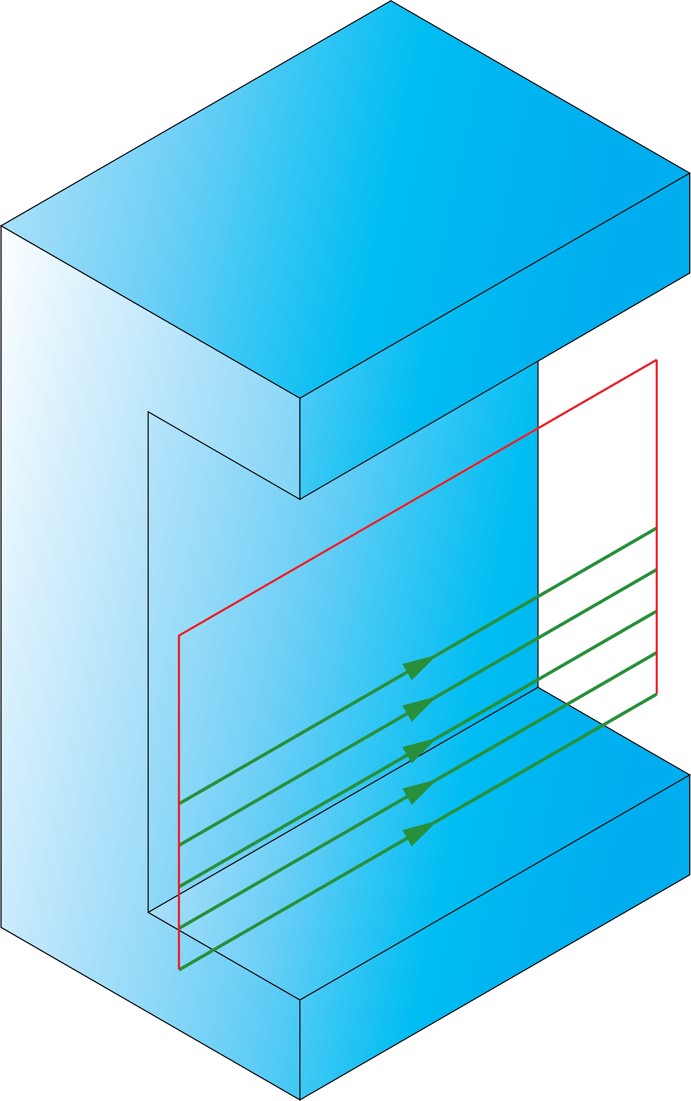
- The One way option enables you to create the tool path for the Clear offset removal containing either climb or conventional movements.
![]()
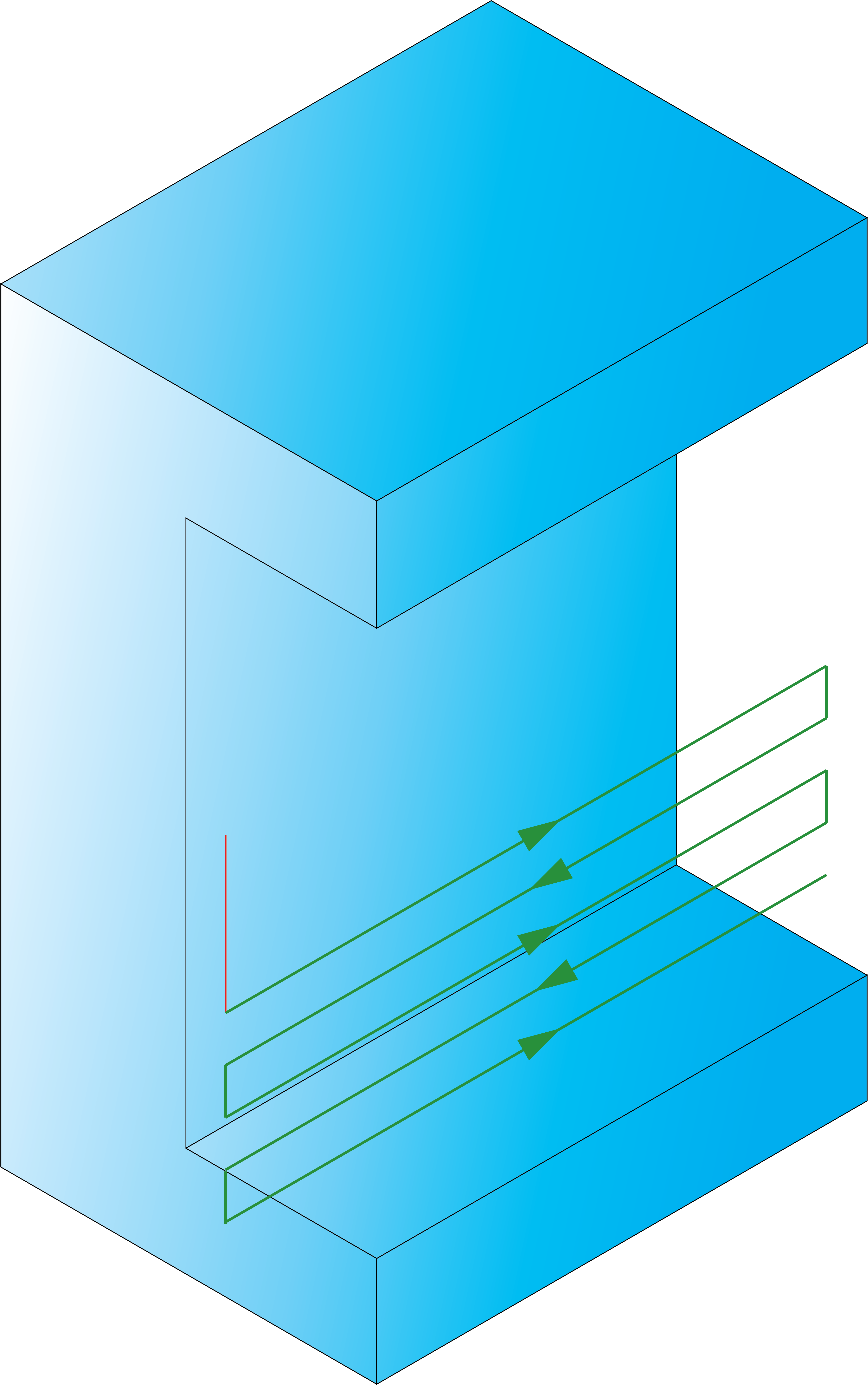
• The Zigzag option enables you to create the tool path for the Clear offset removal containing both climb and conventional movements.
![]()
The Spiral option enables you to create the tool path for the Clear offset removal containing both climb and conventional movements.
![]()
Depth cutting type
![]()
When the One way option is chosen, the cutting passes are oriented in the same direction and connection between them is performed through the Operation Clearance level. At the end of each pass the tool performs a retreat movement to the Operation Clearance level, a horizontal movement at rapid feed to the start point of the next pass and then descends to the Z-level of the next pass. The same cutting direction (climb or conventional) is kept along the whole tool path.
When the Zigzag option is chosen, the tool path is performed in a zigzag manner, with the tool path direction changing from one pass to the next. The passes located at two successive Z-levels are connected directly from the end of one pass to the beginning of the next pass.
|
The Zigzag option cannot be used together with the Clear offset technology. |
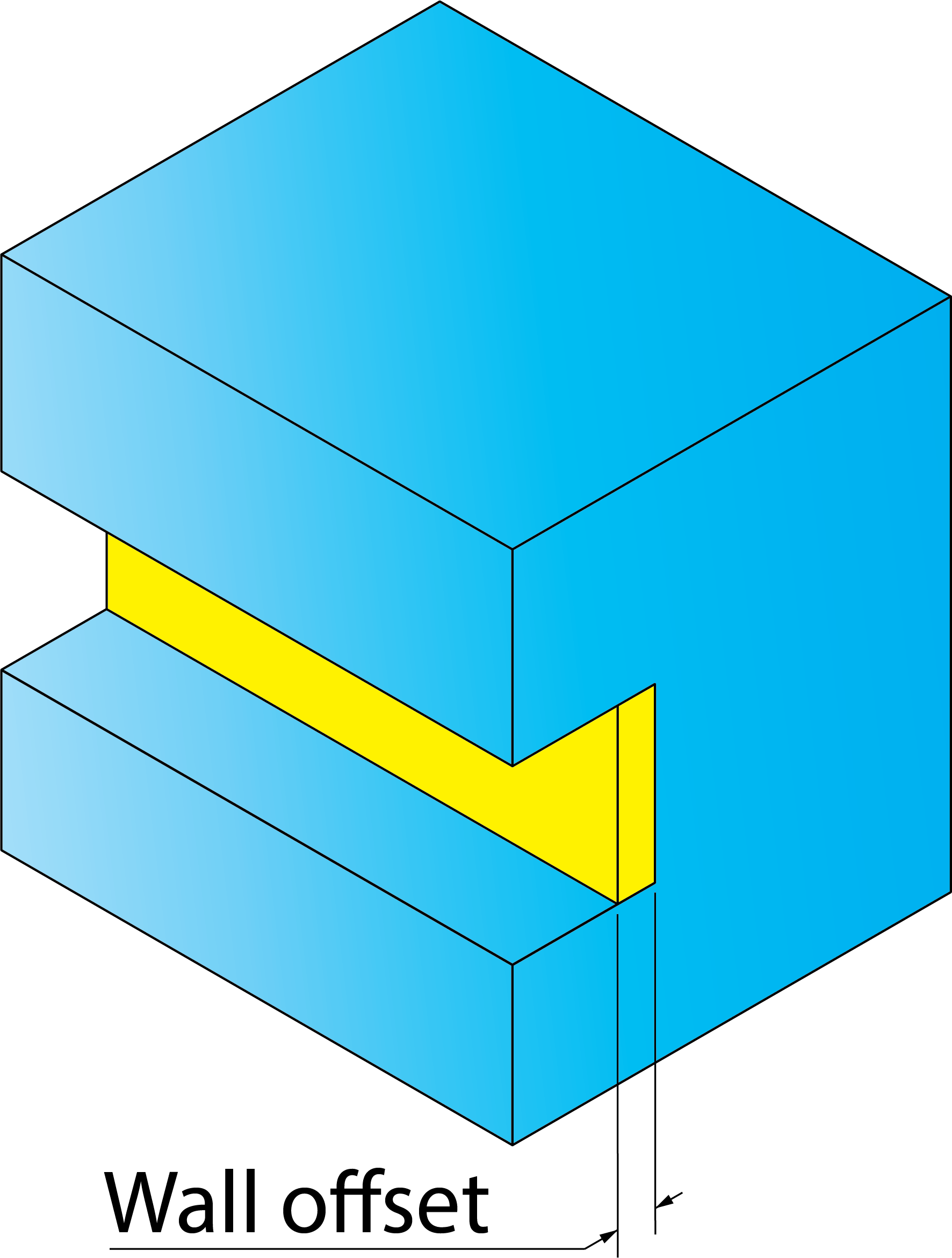
Offsets
To perform the rough machining of the slot, you have to specify various offsets on the slot geometry.
This option defines the offset that will remain on the slot wall after roughing.
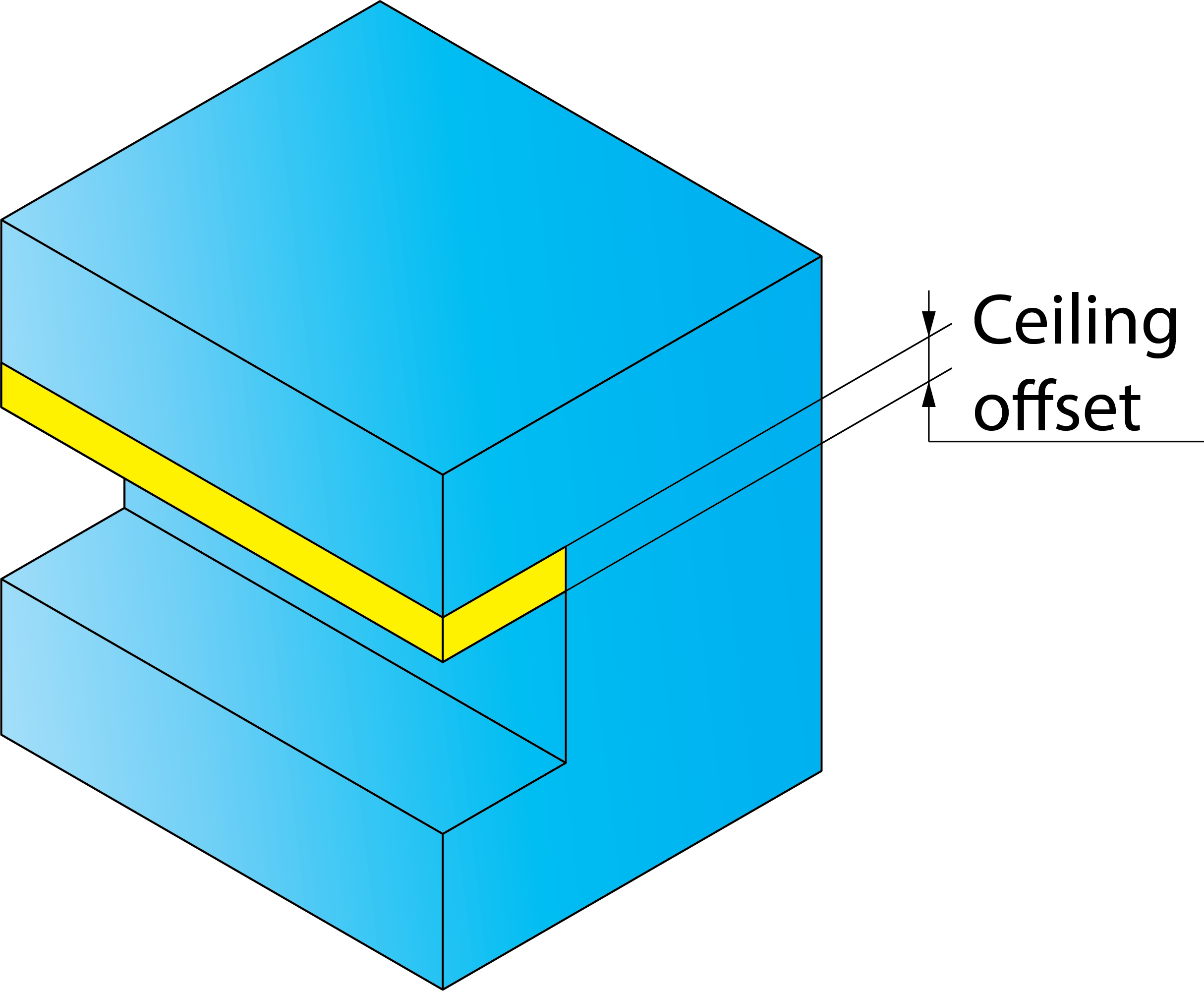
This option defines the offset that will remain on the slot ceiling after roughing.
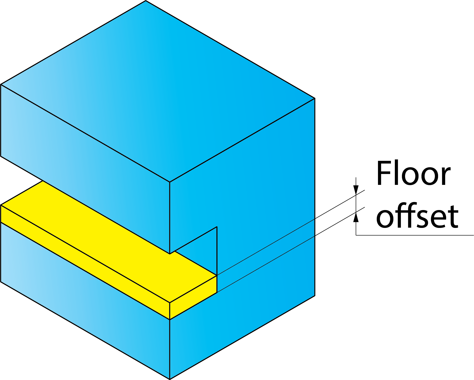
This option defines the offset that will remain on the slot floor after roughing.
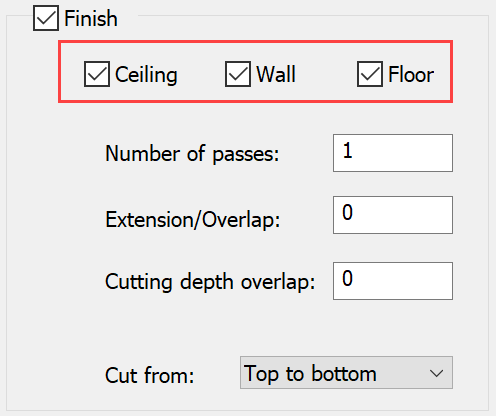
Finish
This section enables you to perform the finishing of the slot.
By selecting the check boxes, you can choose the offsets (Ceiling, Wall and Floor) you want to remove in the finish pass.
SolidCAM enables you to generate several finish passes to achieve the best surface quality. You can define the number of finish passes.
Extension/OverlapThis option enables you to extend the profile in the positive profile direction.
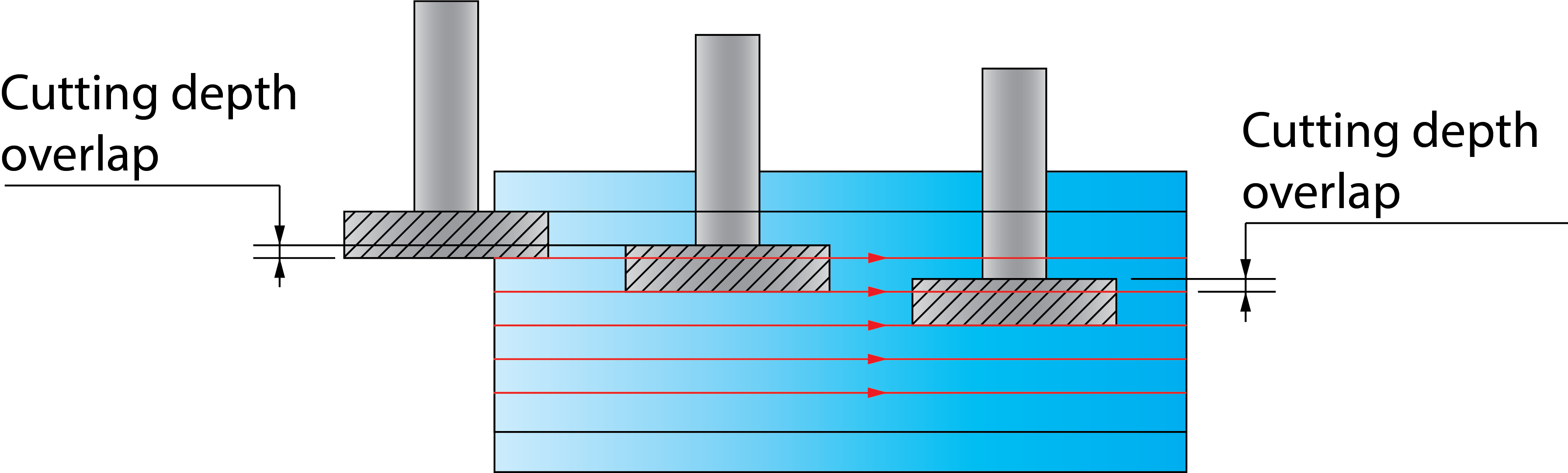
Cutting depth overlap
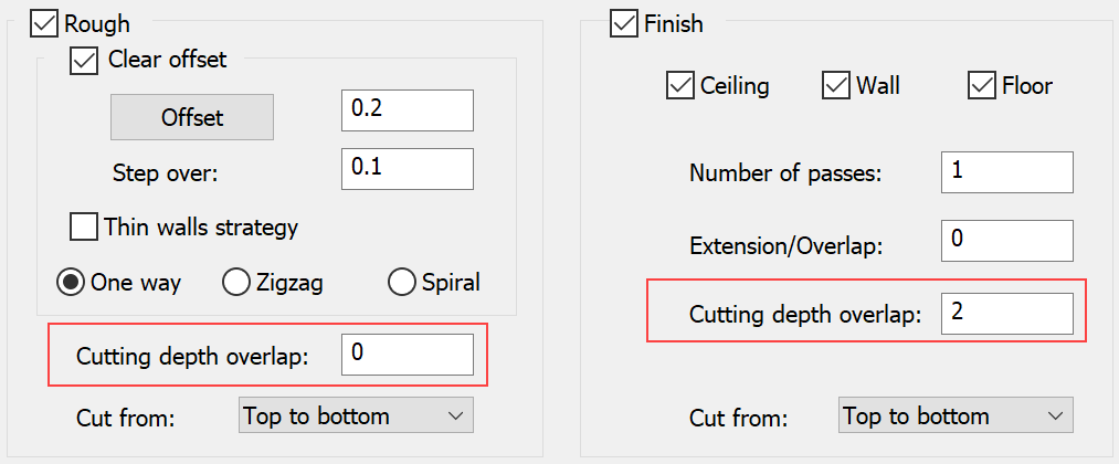
This parameter defines the overlap of each two adjacent tool paths, in both the rough and finish machining of the slot.
Cut from
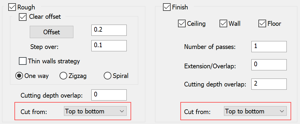
This option enables you to define the direction of machining. The rough and finish machining of the slot can be performed in the following directions:
Top to bottom
Bottom to top
Middle to bottom
Middle to top
Fillet size for last cut
This option enables you to add a radius to a sharp corner without changing the geometry.
Related Topics