Angled cylinder
This ToolBox Cycles strategy enables you to machine an angled surface on a cylinder
Geometry definition
The list of available geometries contains only suitable geometries. Suitable geometries
|
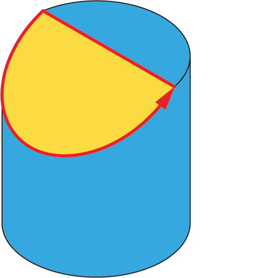 |
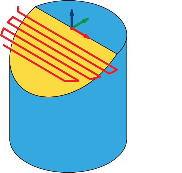
Before the geometry definition, the coordinate system should be defined with the origin located at the cylinder revolution axis. The Z-axis of this coordinate system should be normal to the upper surface. This coordinate system should be used for the geometry definition.
Milling levels
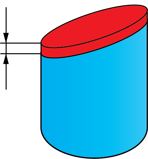
The Upper level is set according to the Part Upper level defined in CoordSys Data.
The Depth is the vertical distance from the top face to the lowest point of circle.
Technological parameters
Step down
This parameter can be defined using one of two options: Max step down or Scallop. The Max step down is the maximal distance between two successive cutting levels. The Scallop is the height of the cusp remaining on the machined surface. |
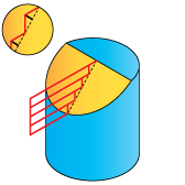 |
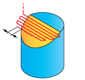
Parallel cuts
The Step over is the distance between two adjacent passes. |
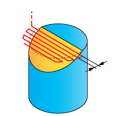 |
The direction of cutting can be either Zigzag or One way. When the One way option is chosen, all the cutting passes are generated in one direction, maintaining the climb milling for all the cuts. When the Zigzag option is chosen, the tool path is generated in the zigzag manner, the direction is changed for each two successive cutting passes.
Offsets
This section enables you to define the Surface offset for this sub-operation. The offset is applied to the inclined surface. |
 |
Extension
During the machining, the tool path is extended over the edges of the inclined surface in order to exit from the material at each cutting pass. The Extension section enables you to define the tool path extension either by percentage of the tool diameter (the % of tool diameter option) or by value (the Value option). |
 |