Tool path tolerance
SolidCAM generates the tool path in two steps:
- SolidCAM generates a mathematical representation of the surfaces and solids of the 3D Model geometry within the given facet tolerance. The information about this triangulation process is stored in an internal *.fct file that is similar to an *.stl file.
- SolidCAM calculates the tool path using the parameters specified for the tool and the milling strategy to calculate the single steps of the tool on the mathematical model created in the first step. The result of this calculation, the *.pj PCode file, later serves as input to the generation of the actual GCode file. During this calculation, SolidCAM uses the Tool path tolerance that affects the number of single steps in the tool path (accuracy of the tool path).
The tool path tolerance can be defined by the following criteria:
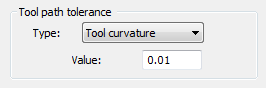
Tool curvature
The accuracy of the tool path depends on the Tool diameter and the specified tolerance value.
Surface curvature
The accuracy of the tool path depends on the surface curvature and the specified tolerance value.
Side step
This tolerance enables you to control the size of a single step that will be constant during the whole tool path.
|
Small tolerance values result in more GCode steps in the GCode file, but the resulting surface is closer to the mathematical model. |