Defining a 3D Model geometry
SolidCAM enables you to define the 3D Model geometry using the 3D Geometry dialog box.
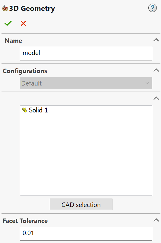
Name
This option enables you to define the name of the geometry. SolidCAM offers you the Default Geometry name that can be edited.
Configurations
This option enables you to switch between SOLIDWORKS configurations. Choose the relevant configuration for the geometry definition.
CAD selection
This option enables you to select the 3D geometry with the SOLIDWORKS tools.
|
When an object is selected in the CAD selection mode, the CAD selection button changes to Resume. |
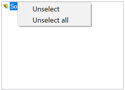
List of selected objects
You can select an object by clicking on it. When an object is selected, its icon is displayed in the list in the bottom of the dialog box.
To unselect the object, click on it again or right-click on its icon in the list and choose Unselect from the menu. To remove selection from all objects in the list, click Unselect all.
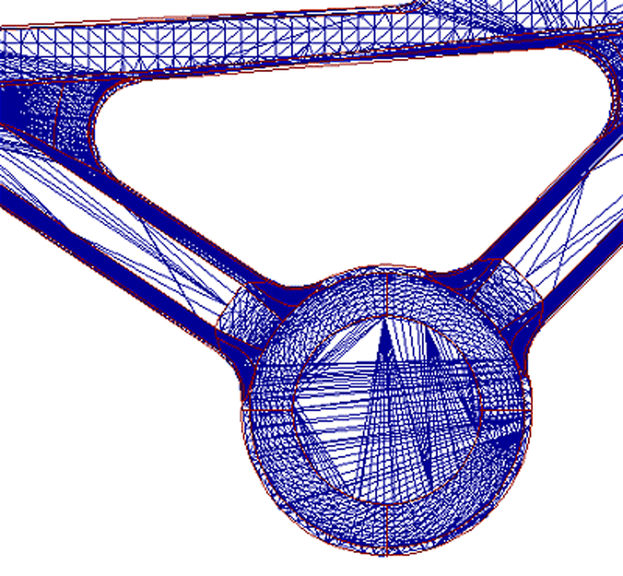
Facet Tolerance
This tolerance controls the maximum deviation of the mathematical representation from the original solids and surfaces of your model.
The 3D Model geometry is triangulated and the resulting facets are saved in the <model_name>.fct file in the CAM-Part's folder. The triangulation is performed on the 3D Model geometry when you use it for the first time. If you use the 3D geometry in another operation, SolidCAM checks the tolerance of the existing *.fct file of this geometry. It does not perform another triangulation as long as the *.fct file is created with the same surface tolerance. |
 |
Related Topics