Understanding the structure of the CNC-Machine
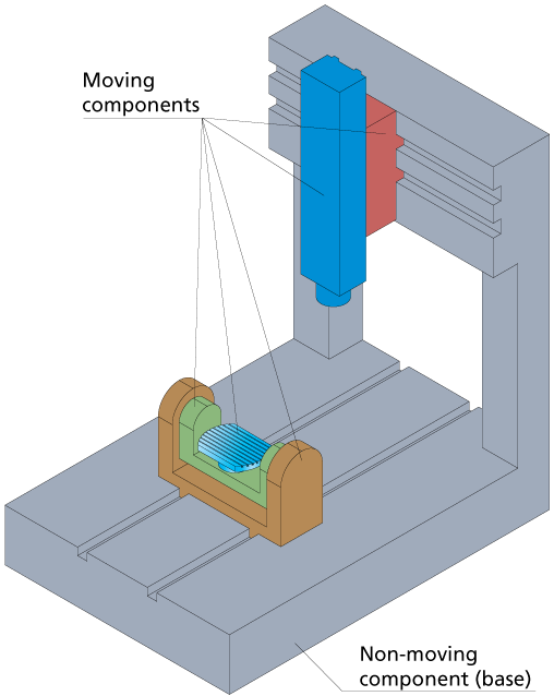
Before defining your CNC-Machine components, you have to analyze the machine kinematics. Generally, all the components of the CNC-Machine can be classified into two groups: non-moving components and moving components. The first group includes the CNC-Machine base, controller, doors, etc. The moving parts are the components of the transitional and rotational axes and the spindle unit.
In case of Table-Table machines, the base is a non-moving component.
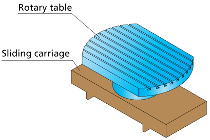
All the moving components can be classified according to the dependency of the movements. For example, in the Table-Table CNC-Machine the rotary table that provides the rotation around the vertical axis (C-axis) is mounted on the tilting table. The tilting table that provides the rotation around the X-axis (B-axis), is mounted on the saddle. The saddle performs the X-axis movements. Movement of the saddle affects the location of the B-axis and C-axis (the tilting and rotary tables are moved). Movement of the tilting table (rotation around B-axis) affects the orientation of the C-axis (the rotary table is moved together with the tilting table), but does not affect the X-axis. The rotary table movement (rotation around C-axis) does not affect the B-axis and X-axis orientation.
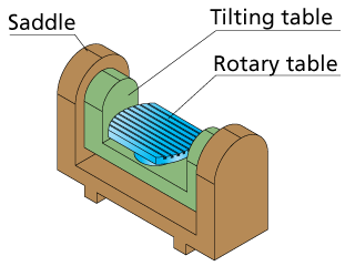
Hierarchically, we can describe the structure of the rotary table, tilting table and saddle using “parents-children” relations. The saddle is the “parent” of the tilting table because the tilting table (“child”) is mounted on the saddle. Similarly, the tilting table is the “parent” of the rotary table because the rotary table is mounted on the tilting table.
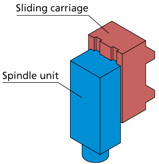
Another separate set of the CNC-Machine components provides the movements in the YZ-plane. The sliding carriage provides movements along the Y-axis, and the spindle unit performs the Z-axis movements. In this hierarchy the sliding carriage is a “parent” and the spindle unit is a “child”.
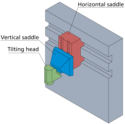
The structure of a Head-Table CNC-Machine can be described by two separate sets of components. The components of these sets are combined together according to the “parents-children” criterion.
The first set consists of the tilting head with the spindle unit (B-axis) mounted on the vertical saddle (Z-axis). The vertical saddle is mounted on the horizontal saddle (X-axis).
The second set consists of the rotary table (C-axis) mounted on the sliding carriage (Y-axis).
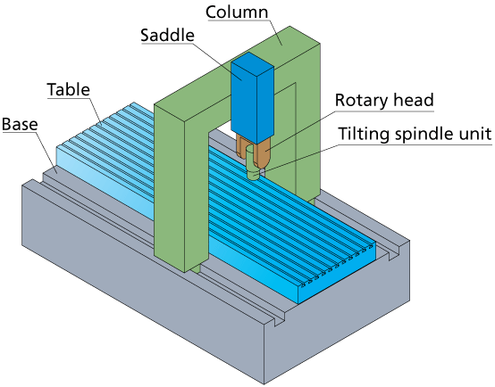
The table of a Head-Head CNC-Machine is a non-moving component mounted on the base. The moving parts are described by the following “parents-children” hierarchy. The tilting spindle unit (B-axis) is mounted on the rotary head (C-axis). The rotary head is mounted on the saddle performing movements in the YZ-plane. The saddle is mounted on the column (X-axis).
The CNC-Machine has to be defined according to the “parents-children” relations between the CNC-Machine components; these relations determine the order of the components definition and dependencies between them.
Related Topics