Modify cutting conditions
This tab enables you to modify any one or more of the Cutting conditions parameters, providing you with additional flexibility and advanced control.
The values appearing on the Modify cutting conditions tab are always those corresponding to Machining level 8 (Normal or Turbo, whichever is the current mode). If you have chosen a level different from 8 on the Machining level slider, you will not get your modified value. In the Output Cutting Data, you will see the newly interpolated value between the original level 1 value and the new value, which you have just entered for level 8.
Override check boxes are available to modify the values that are set by the Technology Wizard, while maintaining synchronization across step down, step over, spindle speed and feed rate.
|
It is strongly recommended to only override any one or more of these parameters if the Machining level slider does not produce your desired result. |
Material Database
The Material Database selection is inherited from the Tool definition.
This list enables you to define a different work material that is associated to the operation.
|
A different work material defined in the operation is an efficient way of machining different materials on a per operation basis. |
Tool Material
The Tool Material selection is also inherited from the Tool definition.
The type of material assigned to the tool cannot be changed using the Modify cutting conditions functionality, but you can manually set a percentage adjustment if necessary. The newly entered value is then used to calculate the Max. Cutting Speed of the tool for the current operation.
Chip Control
Max. Chip Thickness – this value represents the maximum chip thickness for Machining level 8.
Min. Chip Thickness – this value represents the minimum chip thickness for all Machining levels.
Feed Control
Feed Rate Max – this value represents the maximum cutting feed rate for Machining level 8 when the tool is cutting at the minimum cutting angle.
Reposition Feed – this value represents the feed rate for reposition moves when the Z is down in the cut.
Spindle Control
Max. Spin – this value represents the maximum spindle speed for Machining level 8 when the tool is cutting in XY.
Max. Cutting Speed – this value represents the maximum velocity between the edge of the cutting tool and the surface of the workpiece for Machining level 8.
Required Power At Motor – this value represents the power required for Machining level 8.
Cutting Angle Control
Max. Surface Area – this value represents the maximum percentage of surface area contact between the cutting tool and the workpiece for Machining level 8.
Max. Cutting Angle – this value represents the maximum cutting angle for Machining level 8. This value cannot exceed 80°.
Min. Cutting Angle – this value represents the minimum cutting angle for Machining level 8. 10° is the lowest acceptable value.
Level 1 Max. Cutting Angle – this value represents the maximum cutting angle for Machining level 1.
Synchronization of values
In the event that a modified value cannot be synchronized due to limitations of the machine or a mismatch of values, the text field is highlighted in red and a border-crossing arrow icon appears.
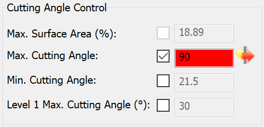
This indicates that you should change the current situation.
There are three ways to resolve the mismatch of values:
- Modify other values that may be responsible, at least in part, for the mismatch until there are no text fields highlighted in red (not an easy task).
- Disable the override check box to restore the original value set by the Wizard.
- Click the border-crossing arrow icon.
When the border-crossing arrow icon is clicked, the Wizard calculates the nearest reconcilable value. The text field is then highlighted in yellow and the newly calculated value is written to the field.
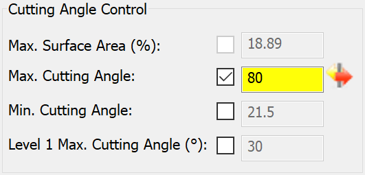
This indicates that the Modify cutting conditions data is validated.
Turbo Mode
This option enables all levels of the Machining level slider to become more aggressive and to yield an estimated 25% higher Material Removal Rate (MRR). This means that the MRR of level 5 Turbo is about 25% more than the MRR of level 5 Normal, and so on. Level 1 Turbo is not the next level after level 8 Normal. If you want more MRR than you get with level 8 Normal, then you should consider using the Turbo Mode.
|
Cooling is just as important as selecting the correct Machining level. Always arrange for perfect cooling. When level 8 Turbo is used, you can cut very fast but heat becomes a problem. And so, more cooling is necessary. |
Since the Cutting conditions are constrained by the machine’s limitations, (e.g., the Wizard cannot set the spindle speed or feed rate higher than the maximum capable by the machine) it is not always possible to increase the MRR by simply increasing the spindle speed or feed rate by 25%. In such cases, the Wizard may have to go back and change other parameters in order to reach the desired 25% increase.
For these reasons, it is not always easy to understand the logic of changes in the values that are displayed in the Output Cutting Data. Do not be concerned however, the Wizard will make sure the end result is as close to your intentions as possible by the machine.