Pocket Ramping options
This section controls the way the tool plunges into the material inside the pocket. Choose the Ramping mode and set the corresponding parameters.
None
The tool enters the material vertically at the start point chosen automatically by the SolidCAM pocket algorithm.
Vertical
![]()
The tool enters the material vertically at a user-defined position. From this position, the tool moves to the pocket start point, calculated by the pocket algorithm.
The Points button displays the Ramping points dialog box that enables you to define the position for the ramping points.
Angle
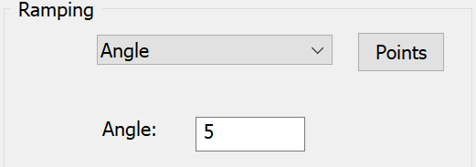
The tool moves to the pocket start point at a specified ramp angle.
The Points button displays the Ramping points dialog box that enables you to define the ramping position and the related parameters.
The Angle edit box enables you to define the ramping angle.
SolidCAM checks the ramping movement against the pocket contour. When the link point is located outside a closed or partially closed contour and can cause the tool gouge, the link point is ignored. The default start point is used instead.
Helical
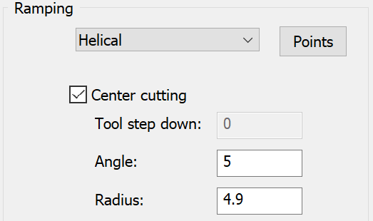
The tool enters the material in a spiral movement according to the following parameters:
Points button – displays the Ramping points dialog box that enables you to define the ramping position.
- Tool step down – defines the distance between each two adjacent turns of the tool helical movement.
- Angle – defines the aggressiveness of the descent angle.
- Radius – defines the radius of the descending helix.
Center cutting
If your tool has center cutting capabilities, select the Center cutting check box. In the Angle field, enter the descent angle that you would like the tool to follow. In the Radius field, enter the radius of the tool path helix.
The working order is as follows:
The tool descends from the safety distance above the Upper level to the material in a circular motion until the step down is reached using the user-defined radius.
When the tool reaches the step down depth, it machines all the material at the step down depth.
When the machining is completed at this depth, the tool goes up to the Clearance level.
At this stage, the tool repositions itself at the Z safety distance above the previous step down depth and repeats the Helical Lead in to the next working depth.
This process repeats itself until the final depth has been machined.
If the tool does not have center cutting capabilities, do not select the Center cutting check box. In the Tool step down field, enter the depth of the step down of the tool.
The result of this action is the same as with a center cutting tool except for the following differences:
The tool descends from the safety distance above the Upper level to the material in a circular motion up to the Tool Step down.
At this point, the tool clears a circular path. Then it descends to the next Tool step down.
This is repeated until the tool reaches the CAM-Part step down depth.
When the tool reaches the step down depth, it machines all the material on that step down depth.
When the machining is completed at this depth, the tool goes up to the Clearance level.
At this stage, the tool repositions itself at the Z safety distance above the previous step down depth and repeat the Helical Lead in to the next working depth.
This process repeats itself until the final depth has been machined.
Linear
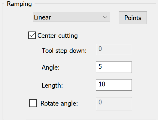
The Linear ramping follows the same rules as the Helical ramping. The difference is that the descent is performed in a linear zigzag manner rather than in a circular one.
The Points button displays the Ramping points dialog box that enables you to define the ramping position.
The Tool step down parameter defines the distance between each two adjacent turns of the tool helical movement.
The Angle parameter defines the ramping angle.
The Length parameter defines the length of the linear descending motion.
The Rotate angle parameter enables you to the rotate the linear zigzag tool descent at an angle specified in the Rotate angle field. The Rotate angle defines the angle of descent relative to the origin i.e. the X axis. If a positive Rotation angle is set the linear zigzag ramping is rotated in one direction and reversed for negative Rotation angle.
Center cutting
If your tool has center cutting capabilities, select the Center cutting check box. In the Linear dialog box, enter the length of the linear tool path that you would like the tool to travel.
The working order is as follows:
The tool descends from the safety distance above the Upper Level to the material in a zigzag motion based on the user defined angle and length until the step down is reached.
When the tool reaches the down depth step, it machines all the material on that step down depth.
When the machining is completed at this depth, the tool goes up to the Clearance level.
At this stage, the tool repositions itself at the Z safety distance above the previous step down depth and repeat the Linear Lead in to the next working depth.
This process repeats itself until the final depth has been machined.
If the tool does not have center cutting capabilities, do not select the Center cutting check box. In the Tool step down field, enter the required depth of the step down.
The result of this action is the same as that of the center cutting tool except for the following differences:
The tool descends from the safety distance above the Upper Level to the material in a zigzag motion up to the Tool Step down.
At this point the tool clears a straight linear path. Then it descends to the next Tool Step down.
This is repeated until the tool reaches the CAM-Part step down depth.
When the tool reaches the step down depth, it machines all the material on that step down depth.
When the machining is completed at this depth, the tool goes up to the Clearance level.
At this stage, the tool repositions itself at the Z safety distance above the previous step down depth and repeat the Linear ramping to the next working depth.
This process repeats itself until the final depth has been machined.
SolidCAM checks the ramping movement against the pocket contour. When the link point is located outside a closed or partially closed contour and can cause the tool gouge, the link point is ignored. The default start point is used instead.
Related Topics