Composite tool - External Turning
Insert Definition
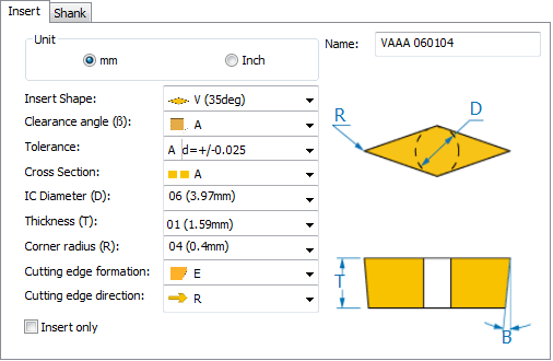
| Insert Shape | The shape of the insert |
| B (Clearance angle) | The insert clearance angle |
| Tolerance | The set of tolerance values for d, m, and s parameters |
| Cross Section | The insert cross section |
| IC Diameter (D) | The insert diameter |
| Thickness (T) | The insert thickness |
| Corner radius (R) | The insert corner radius |
| Cutting edge formation | The shape of the cutting edge |
| Cutting edge direction | The orientation of the tool: Left, Right or Neutral. The offset point of the tool moves from the left to the right side, right to left side or remains in the Neutral position depending on the Cutting edge direction selection. |
The Insert only option enables you use the insert without the shank, if you want to mount the cutting insert on an STL holder.
The this option is selected, the Shank page is disabled, and the Insert lead angle field is displayed enabling you to set the position of the insert without rotating the whole tool.
Shank Definition
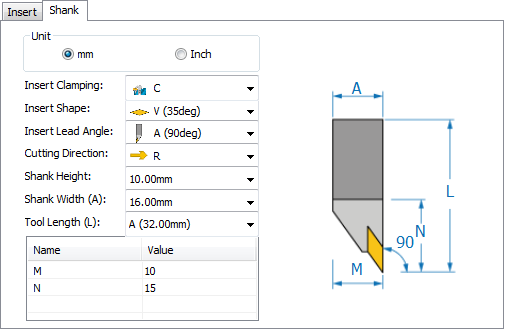
| Insert Clamping | The type of clamping |
Insert Shape |
The shape of the insert |
| Insert Lead Angle | The angle between the cutting edge and material surfaces |
| Cutting Direction | The side of shank on which the insert is mounted. |
| Shank Height | The height of the shank |
| Shank Width (A) | The width of the tool shank |
| Tool Length (L) | The height of the tool from the top to bottom point (including insert) |
| M | The length of the flat area |
| N | Insert overhang distance |
|
The External Turning Composite tool supports Cut-off operation also. |
Related Topics