Tool Table dialog box
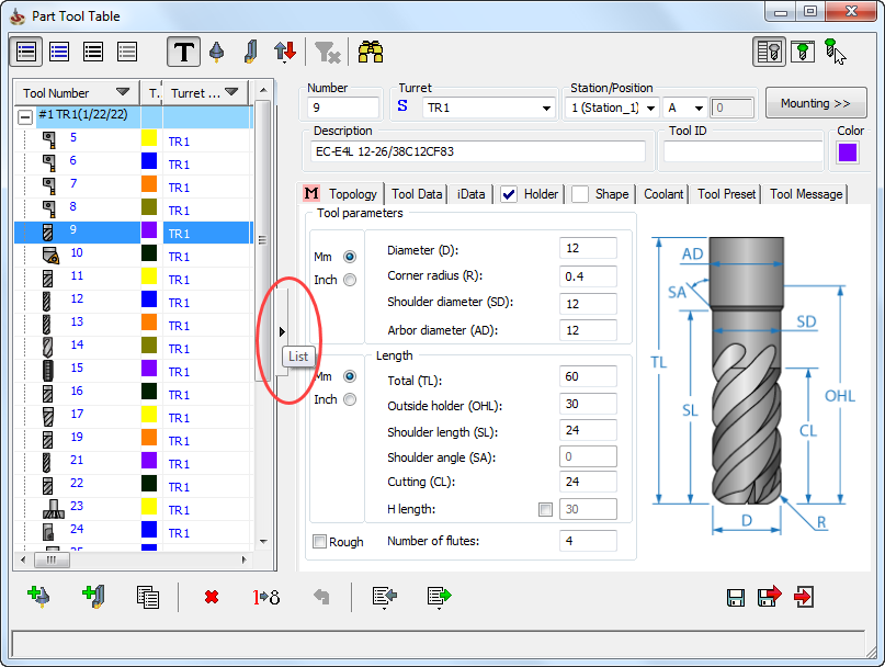
The Tool Table dialog box contains structured information about all tools included in the specified tool library. This dialog box enables you to add new tools to the tool library, remove tools from the tool library, edit the tool definition, etc.
The buttons at the top of the dialog box enable you to manage the dialog box content:
 All tools
Click this button to display all the tools defined in the tool table.
 Tools
used in operations
Tools
used in operations
Click this button to display only the tools used in operations of the current CAM-Part.
 Unused
tools
Unused
tools
Click this button to display only the tools that were not used in operations of the current CAM-Part.
 Tools
used in suppressed operations
Tools
used in suppressed operations
Click this button to display only the tools used in suppressed operations of the current CAM-Part.
 Show
Turrets
Show
Turrets
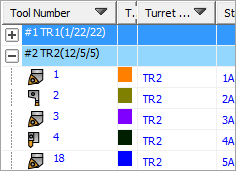
Click this button to display the tools in groups according to the turrets they are mounted on. The group title includes the turret name and tools statistics in parenthesis. The first number shows the number of stations; the second is the total number of tools; the third is the number of tools used in the current CAM-Part.
 Show
Milling
Show
Milling
Click this button to display only the Milling type tools defined in the tool table.
 Show
Turning
Show
Turning
Click this button to display only the Turning type tools defined in the tool table.
 Show
First
Show
First
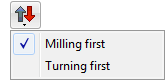
Click this button to choose the type of tools (Milling or Turning) that you would like to appear first in the list.
 Clear
filter
Clear
filter
Click this button to cancel the filter conditions applied to manage the tool table content.
 Find
Find
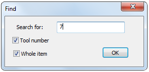
This button displays the Find dialog box that enables you to perform search in the Tool Table dialog box.
 List
List
This button enables you to toggle the display of the Tool parameters area of the dialog box.
|
You can also toggle the display of the Tool
parameters area by clicking on the List
arrow in the Tool Table dialog box.
 |
 Show
tool
Show
tool
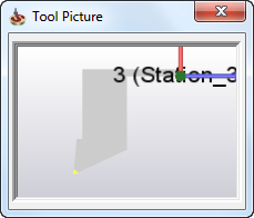
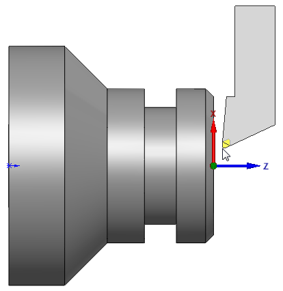
This button displays the chosen tool in the Tool Picture window. The tool is displayed together with the CAM-Part Coordinate System and can be dynamically zoomed and rotated.
 Visual tool check
This button displays the half-transparent image of a tool selected in the Part Tool Table dialog box that follows the cursor moving over the model. The tool image can be dynamically zoomed and rotated together with the model.

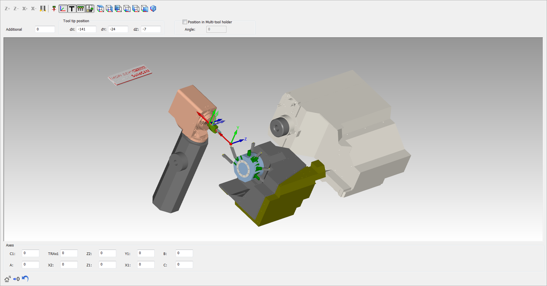
This button displays the Mounting dialog box that contains parameters related to the tool mounting on the CNC-Machine as shown below.
 Add
Add
This option enables you to add a new tool to the tool library.
 Copy
Copy
This option enables you to create a copy of an existing tool.
 Delete
This option enables you to delete the selected tool.
 Renumber
This option enables you to renumber the tools.
More...
 Undo
Undo
This option enables you to call off the last command.
 Import
This option enables you to import tools to the Part Tool Table from the Current Tool Library or any other Tool Library.
More...
 Export
This option enables you to import the tools data to an Excel-compatible file.
Tool table customization
The right-click menu available on the column names enables you to customize the tool table. Select the parameters that you want to appear as columns in the table.
Save and Exit
![]() enables you to Save the current state of the tool
table without exiting the dialog box.
enables you to Save the current state of the tool
table without exiting the dialog box.
 enables you to Save
all recent changes and Exit
the Part Tool Table dialog box.
enables you to Save
all recent changes and Exit
the Part Tool Table dialog box.
 enables you to Exit
the Part Tool Table dialog box without saving the recent changes.
enables you to Exit
the Part Tool Table dialog box without saving the recent changes.
Related Topics