Technology page
This page enables you to define the technological parameters of the machining.
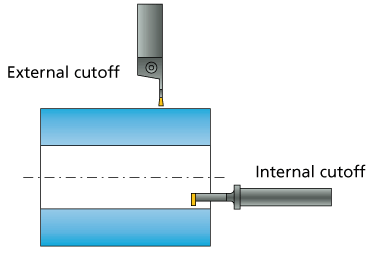
Mode
This section enables you to set the machining mode.
- Long external
- Long internal
Tool side
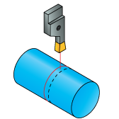
This section enables you to define the tool location relative to the geometry during the Cutoff operation.
The tool cuts to the left of the geometry. |
|
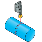
The tool cuts to the right of the geometry. |
|
The tool center is located on the geometry. |
|

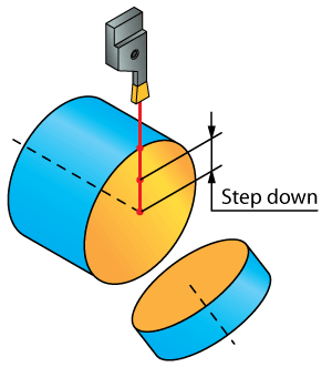
Step down
This section enables you to define the type of the step down movements and specify the Step down value.
Constant
When this option is chosen, machining is performed in several steps. You are prompted to specify the constant Step down value. After each step down the tool retreats from the material according to the defined Release distance.
Single
When this option is chosen, the machining is performed in one step.
Release distance
This section enables you to define the distance for the tool to retract to after each step down and the way the tool retreats from the material.
After cut retract
This section enables you to modify the way the tool retracts from the material. You can define the retraction either in Z- or in Z+ direction. The Retract distance edit box allows you to set a specific distance the tool travels in the Z-axis.
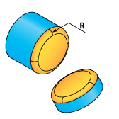
Corner
This option enables you to machine a chamfer or a fillet to the corners formed by the cutoff operation.
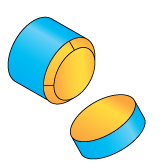
None
Only the cutoff cutting pass is generated, no special machining of corners is performed.

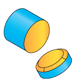
Chamfer
This option enables you to perform chamfer machining of the corners. When you choose this option, SolidCAM enables you to define the chamfer parameters by the following options:
Angle
This option enables you to define the chamfer by angle and distance. The Angle parameter defines the chamfer angle. The Distance parameter defines the chamfer distance along the Z-axis.

Distance
This option enables you to define the chamfer by distances along the X- and Z-axes.

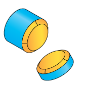
This option enables you to perform fillet machining of the corners. When you choose this option, specify the radius of the fillet in the Fillet parameters section. |
 |
Location
This section enables you to define the location of the applied chamfer/fillet.
The chamfer/fillet is generated to the left of the cut. |
|
The chamfer/fillet is generated to the right of the cut. |
|
The chamfer/fillet is generated on both sides of the cut. |
|
Use cycle
This option enables you to define whether the turning cycles of the CNC-Machine are used or the tool path movements are generated by SolidCAM.
The following options are available:
Yes
The program updates the geometry according to the tool shape and generates the GCode for the CNC-controller cycle including the parameters needed to execute the cycle and the GCode of the updated geometry.
No
The program updates the geometry according to the tool shape and then calculates the minimum tool movements needed taking into account the material boundary at the start of the operation.
Cut
Machine groove cycles are used for every vertical cutting step.
Related Topics