Rough grooving parameters
The Rough tab enables you to define the parameters of the Rough type of grooving.
|
This tab is available only when the Work type is set to Rough. |
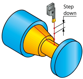
Step down
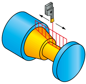
This section enables you to define the type of the step down movements and specify the step down for grooving.
|
The groove depth is divided into several constant steps. The size of each step is defined in the Value field. After each step down the tool retreats from the material according to the defined Release distance. |
 |
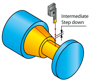
The Intermediate step down option enables you to divide each step down depth into a number of smaller steps, the size of each smaller step is defined in the corresponding Value field. |
 |
|
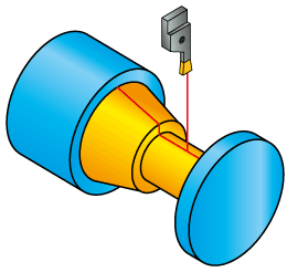
When this option is chosen, the machining is performed in one step. |
 |
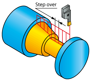
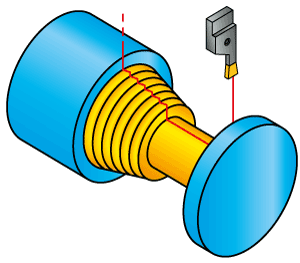
Step over
This parameter defines the sideways distance between each two successive groove-cut steps; this distance should be smaller than the tool width. Scallop - This value determines the quality of the resulting surface on the floor of the slot. The smaller the value, the smoother is the surface.
|
 |
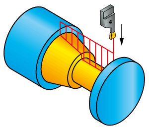
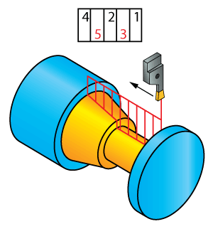
Cutting order
This section enables you to define the ordering of grooving cuts.
|
This section is available only when the Step down type is set to Constant. |
|
The cutting area is divided horizontally into a number of rows along the machining axis. The height of each such row is defined with the Step down parameter; the width of each step in the row is defined with the Step over parameter. When all the grooving cuts for a certain row are completed, the tool proceeds to the next row, and so forth. |
 |
|
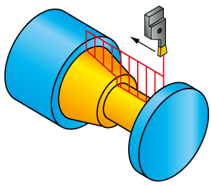
The cutting area is divided vertically into a number of columns perpendicular to the machining axis. The width of each column is defined with the Step over parameter. The columns are machined in a sequential order. |
 |
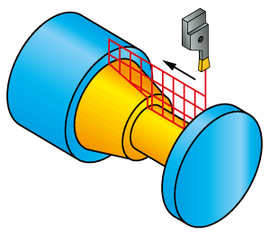
Direction
This section enables you to define the manner of the grooving cutting passes distribution.
|
Cutting passes are performed in the direction defined by the geometry (taking into account the geometry modification). |
 |
||
|
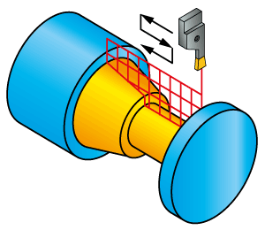
Cutting passes are performed in the zigzag manner: the machining direction is changed from one row to another.
|
 |
||
|
Cutting passes are performed from the middle of the cutting area outwards first in one direction, than in the other. |
 |
||
|
Cutting passes are performed in the direction defined by the geometry; first the odd rows/columns are machined, then the even rows/columns are machined. |
 |
||
|
Cutting passes are performed in the direction defined by the geometry by alternating the machining of the odd rows/columns with machining of the even rows/columns. |
 |
Rough type
This section enables you to define the walls machining type.
|
This section is available only when the Direction is set to From middle outside. |
|
At the end of every pass, the tool continues moving along the geometry until it meets the previous pass; then it retreats from the material. This type of turning results in a smooth material boundary. |
 |
|
At the end of every pass, the tool retreats away from the material. This type of turning results in a stairs-shaped material boundary. |
 |
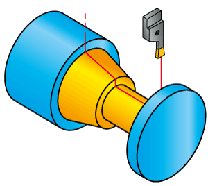
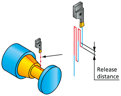
Release distance
This section enables you to define the distance for the tool to retract to after each step down and the way the tool retreats from the material.
|
After machining of a specific step down level, the tool retreats from the material in the Rapid mode to a level equal to the safety distance above the starting point of the groove material. Then it descends into the material again in the Rapid mode till the level equal to the Release distance above the depth of the step down level. Then it feeds in for the next step down with the working feed, and so on.
|
 |
||
|
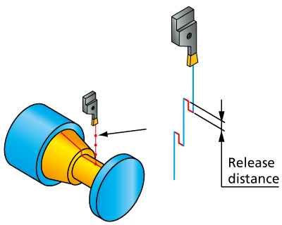
After machining of a specific step down level, the tool retreats from the material in the Rapid mode to a height equal to the Release distance above the depth of the step down level. Then it feeds in for the next step down with the working feed, and so on. |
 |
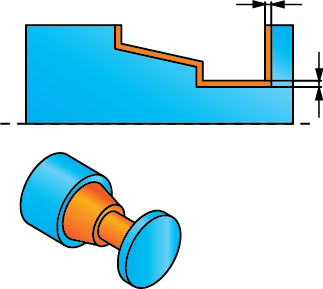
Rough offset
This section enables you to define the offset from the geometry that will remain after the roughing stage of the operation.
|
This option enables you to define the constant offset distance from the geometry. |
 |
|
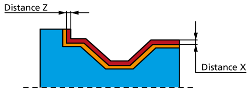
This option enables you to define different offsets from the geometry in the X- and Z-axis directions. The Distance X parameter defines the offset in the X-axis direction. The Distance Z parameter defines the offset in the Z-axis direction. |
 |
|
This option is similar to the ZX option except that the program chooses the sign of the delta-X and delta-Z vector components so that the offset geometry does not intersect the profile geometry. |
 |