Simulation Properties
This page enables you to edit the options that affect the simulation when it is running and the tool path visualization.
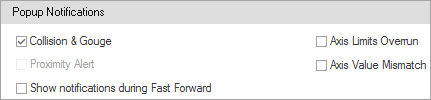
Popup Notifications
This section enables you to turn on/off the display of notifications in case of the following events reported:
|
 |
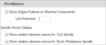
Miscellaneous
This section enables you to activate the following miscellaneous features during simulation:
• Set the Spindle Arrows Display options by selecting Show rotation direction arrows for Tool spindle and/or, Show rotation direction arrows for Stock/Workpiece Spindle check box. |
 |
Toolpath Backplot
This section enables you to customize the following tool path visualization options: Toolpath LineThis option sets the line thickness of the displayed tool path. Segment LengthThis option sets the length of tool path segments displayed when running the simulation in the Follow/Trace modes. Axis Vector LengthThis option sets the length of the tool tilting vector when running the simulation in the Tool Vectors mode. This length can be set as a value or as the radius of the tool used for the operation. Clicking the Color tile enables you to specify the color of the vectors visualization. Toolpath pointsThis option sets the size (in pixels) of the tool path points when running the simulation in the Toolpath Points mode. Clicking the Color tile enables you to specify the color of the points visualization. Color Automatic/Manual The option of automatic coloring of Tool Axis Vectors and Tool Path Points draws these graphics elements with colors similar to the tool path line color. It works best with tool path analysis option of Tool Number and Operation Number. |
 |
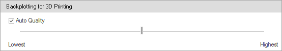
Backplotting for 3D printing
This feature provides a fast and high-quality display of material deposition. The option is available once an additive “tool” is defined. The Auto Quality check box determines your computer power and uses proper drawing methods that offer you the best balance between quality and performance. |
 |
Reset
Clicking Reset Page Settings enables you to return all the customized settings of the current page to the defaults. |
 |