SolidVerify simulation toolbar
The toolbar enables you to control the simulation in the SolidVerify simulation mode.
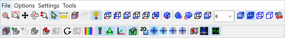
Available buttons:
|
Fit to window This button fits the CAM-Part to the entire screen. |
|
Fit by box The area you want to view in the simulation screen is defined by a box. |
|
Move This button moves the CAM-Part to any point on the screen. |
|
Rotate When you click on this button, the model can be rotated. |
|
Zoom When you click on this button, the image on the screen can be zoomed in/out. |
|
Selection mode The Selection mode enables you to select the solid bodies in the SolidVerify simulation window. The selected body will be highlighted. The right-click menu is available for the each selected solid body. |
|
Measurement The Measurement function enables you to measure distances directly on the solid bodies in the SolidVerify window. This enables checking the linear dimensions of the part during simulation. |
|
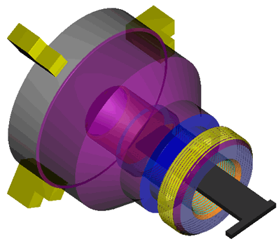
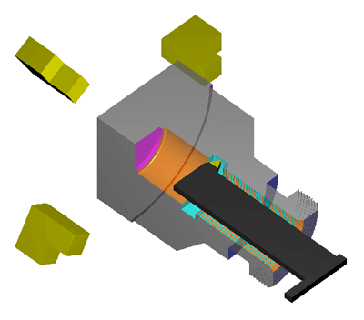
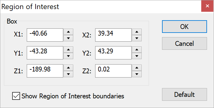
Region of interestThese buttons enable partial display of the simulated workpiece to focus on certain areas that can be specified.
The
In the Box section, you can specify the coordinates of the upper and the lower planes of the boundary box that limits your region of interest. Selecting the Show Region of Interest boundaries check box displays the edges of the box that limits your region of interest.
The |
|
Light control This command enables you to change the light source on the solid model in the Simulation mode. To change the light source, click on any location inside the Graphics view, hold the button down and drag the cursor around within the bounds of the view. |
|
View buttons These buttons enable you to view the CAM-Part in the top, left, back, bottom, right or front views. |
|
Isometric views button This button enables you to view the CAM-Part in the isometric view. |
|
ZX This button enables you to view the CAM-Part in ZX work plane. |
|
Tool location This combo box enables you to control the tool location on the model. |
|
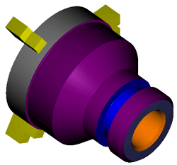
Render mode This button displays a shaded view of the model.
The part will be displayed in the chosen mode (Render, Hybrid, Wire, or Hidden line) next time you play the simulation. |
|
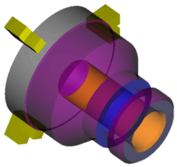
Hybrid mode
This button displays a transparent view of the model.
|
|
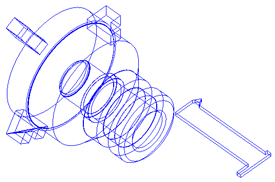
Wire mode
This button displays the CAM-Part and tool movements in wireframe mode.
|
|
Hidden line mode
This button displays the CAM-Part and the tool movements in hidden line wireframe mode.
|
|
Redraw
This button refreshes the screen, but does not rebuild the part. |
|
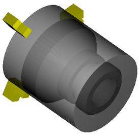
Show/Hide Machined StockThis button toggles the display of the machined stock model. |
|
Load Target fast using CAD facettingThis icon enables you to load the target model with the tolerance value defined in the CAD model. The target is loaded faster, but visualization can be not accurate. |
|
Load Target using CAM facettingThis icon enables you to load the target model with the tolerance value defined in the CAM model. The target is loaded slowly, and visualization is more accurate than with CAD facetting. |
|
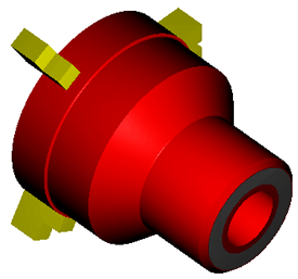
Show/Hide TargetThis button toggles the display of the target model.
This button is disabled if you have not chosen the facetting type of the target model loading (CAD/CAM). |
|
Show/Hide Rest MaterialThis button toggles the display of rest material on the machined stock model.
This button is disabled if you have not chosen the facetting type of the target model loading (CAD/CAM). |
|
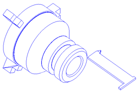
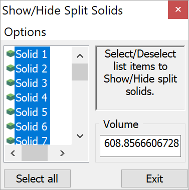
Split Rest MaterialThis option displays the Show/Hide Split Solids dialog box.
This dialog box enables you to switch between split pieces of rest material during the simulation. |
|
Show/Hide GougesThis button toggles the display of gouges on the target model.
|
|
Split GougesThis option displays the Show/Hide Split Solids dialog box. This dialog box enables you to switch between split solids during the simulation and to remove the pieces of material that have been cut away during the machining. |
|
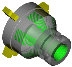
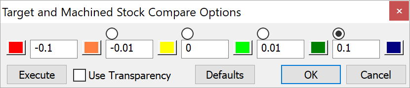
Compare target and machined stock This option enables you to compare the stock model and target model and assign different colors to different rest material areas, depending on their tolerance.
This button is disabled if you have not chosen the facetting type of the target model loading (CAD/CAM). |
|
Show/Hide ToolThis button toggles the display of the tool during simulation. |
|
Show/Hide HolderThis button toggles the display of the tool holder during simulation. |
|
Show/Hide current home This button toggles the display of the coordinate system used in the current operation. |
|
Show/Hide FixtureThis button toggles the display of the fixture during simulation. |
|
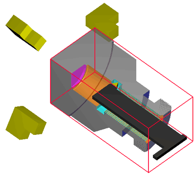
Set turning 2D mode This button displays a section of the model.
|
|
Show section view These buttons enable you to display section views of the turned CAM-Part. You can set the lathe in view full/three quarter/half or quarter mode. |
|
Split/Unsplit Machined StockThis option displays the Show/Hide Split Solids dialog box.
This dialog box enables you to switch between split stock solids during the simulation. |
|
Activate/Deactivate initialization of machined stock This option is used in the case of single operation simulation. If this option is chosen, SolidCAM enables you to perform the simulation on the stock machined by previous operations. If this option is not chosen, SolidCAM performs the simulation on the original unmachined stock model. |
|
Multi-core support This option enables you to perform multicore calculation of the simulation. It means that the CPU performance of your computer is optimized in such a way that allows simultaneous calculation of different elements by different central processing units (cores). In this case, the animation is faster, but looks less accurate. |

Related Topics