Stock definition - Cylinder
This option enables you to define the Stock boundary as a cylinder surrounding the selected Solid model.
When you click on the solid body, SolidCAM generates a sketch that contains the envelope of the cylinder around the selected solid body. This sketch defines the geometry of the Stock.
SolidCAM enables you to define the cylindrical stock by specifying offsets of the cylinder faces from the selected solid body or coordinates of its boundaries relative to the CAM-Part Coordinate System.
Relative to model
When the Relative to model option is chosen for Mode, the cylinder is defined by offsets from the solid model faces.
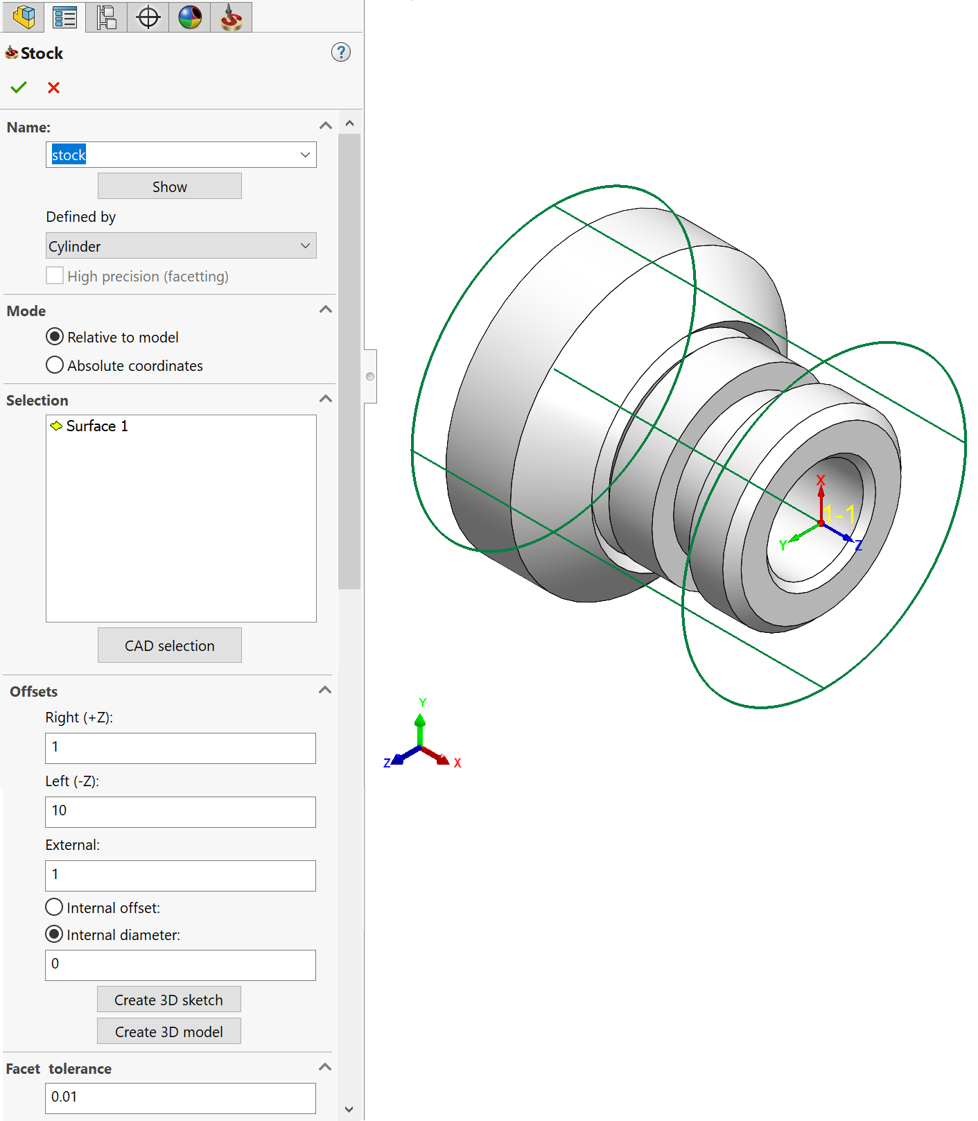
Offsets
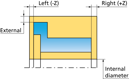
The Right (+Z) and Left (-Z) parameters define the offsets of the front and back cylinder faces from the front and back faces of the solid body, respectively.
The External parameter defines the offset of the external cylinder face from the external face of the solid body.
The Internal offset is associative to the solid model. A positive value would move it away from the Internal diameter towards '0' and a negative value would move it away from the Internal diameter towards the External Diameter.

If the CAM Part is a solid (No Hole) only the Internal diameter is enabled even if you have selected Internal offset in the CAM Part Settings.
The Internal diameter parameter defines the internal diameter of the tube (when the Internal diameter value is greater than 0, a tube is defined for Stock boundary).
- Create 3D sketch
Create 3D sketch button enables you to add a 3D sketch of the cylinder stock to the CAM component of the part assembly.
- Create 3D model
Create 3D model button enables you to add a 3D model of the cylinder stock to the CAM component of the part assembly.
Absolute coordinates
When the Absolute coordinates option is chosen for Mode, the cylinder is defined by specifying coordinates relative to the CAM-Part Coordinate System.
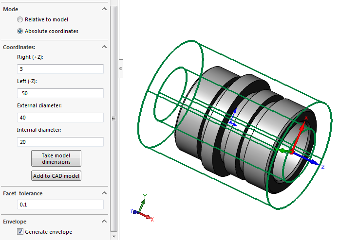
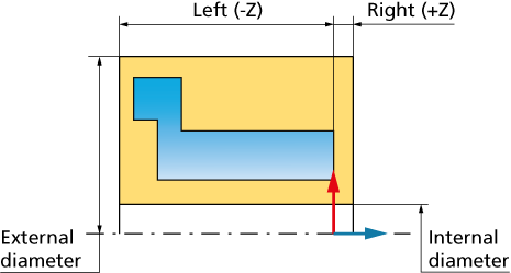
The Right (+Z) and Left (-Z) parameters define the Z-coordinates of the cylinder front and back faces.
The External diameter parameter defines the diameter of the cylinder external face.
The Internal diameter parameter defines the internal diameter of the tube (when the Internal diameter value is greater than 0, a tube is defined for Stock boundary).
Take model dimensions enables you to display the dimensions of the cylinder surrounding the model in the respective coordinates fields.
- Add to CAD model button enables you to add a 3D sketch of the cylinder stock to the CAM component of the part assembly.
|
The cylinder defined by absolute values is not associative to the solid model. |
Related Topics