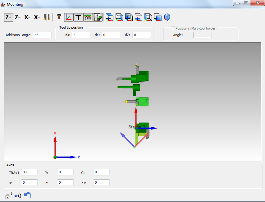
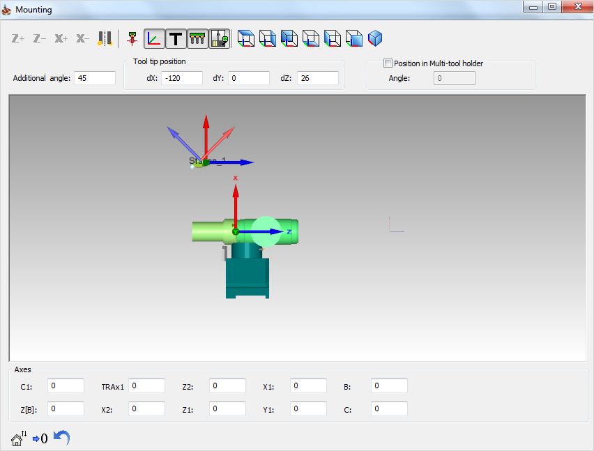
Mounting dialog box
The Mounting dialog box contains the parameters that define the tool mounting on the CNC-Machine. The availability of parameters (e.g., Tool tip position and Axes) are determined by those specifically supported by your machine.
The dynamic 3D preview window enables you to visualize the schematic position of the tool relative to the machine station and turret. Using the right-click menu, you can manipulate the current view.
General parameters
Flip  enables
you to turn the tool around its axis.
enables
you to turn the tool around its axis.
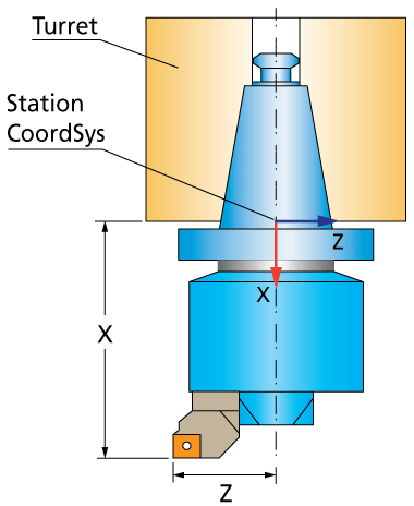
The Tool tip position option enables you to define the tool tip position relative to the station Coordinate System for Machine Simulation.
|
The dX and dZ Tool tip position values remain unchanged when you toggle the view of the tool mounting from one turret to the other. |
Tool mounting on Rotary/Linear turrets
Tool mounting on Spindle turrets
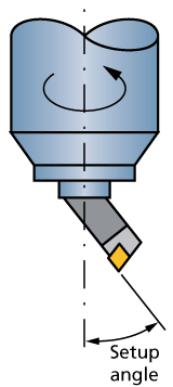
Setup angle/Additional angleThis parameter defines the angle of the tool axis relative to the default tool direction on the station.
Position in Multi-tool holderWhen your tool holder supports multiple tools, this option provides the possibility to rotate the turret around the Spindle axis in angle increments defined by the Min. Angle Step Around Spindle Axis parameter in the Machine ID file (*.vmid). |
 |
|
This option is not available when the Min. Angle Step Around Spindle Axis parameter is set to 0. |
The rest of the available buttons are described in the Machine Preview topic.