Constraint Boundaries
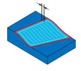
SolidCAM enables you to define the constraint boundaries for the SolidCAM Geodesic Machining operation tool path. A constraint boundary enables you to limit the machining to specific model areas.
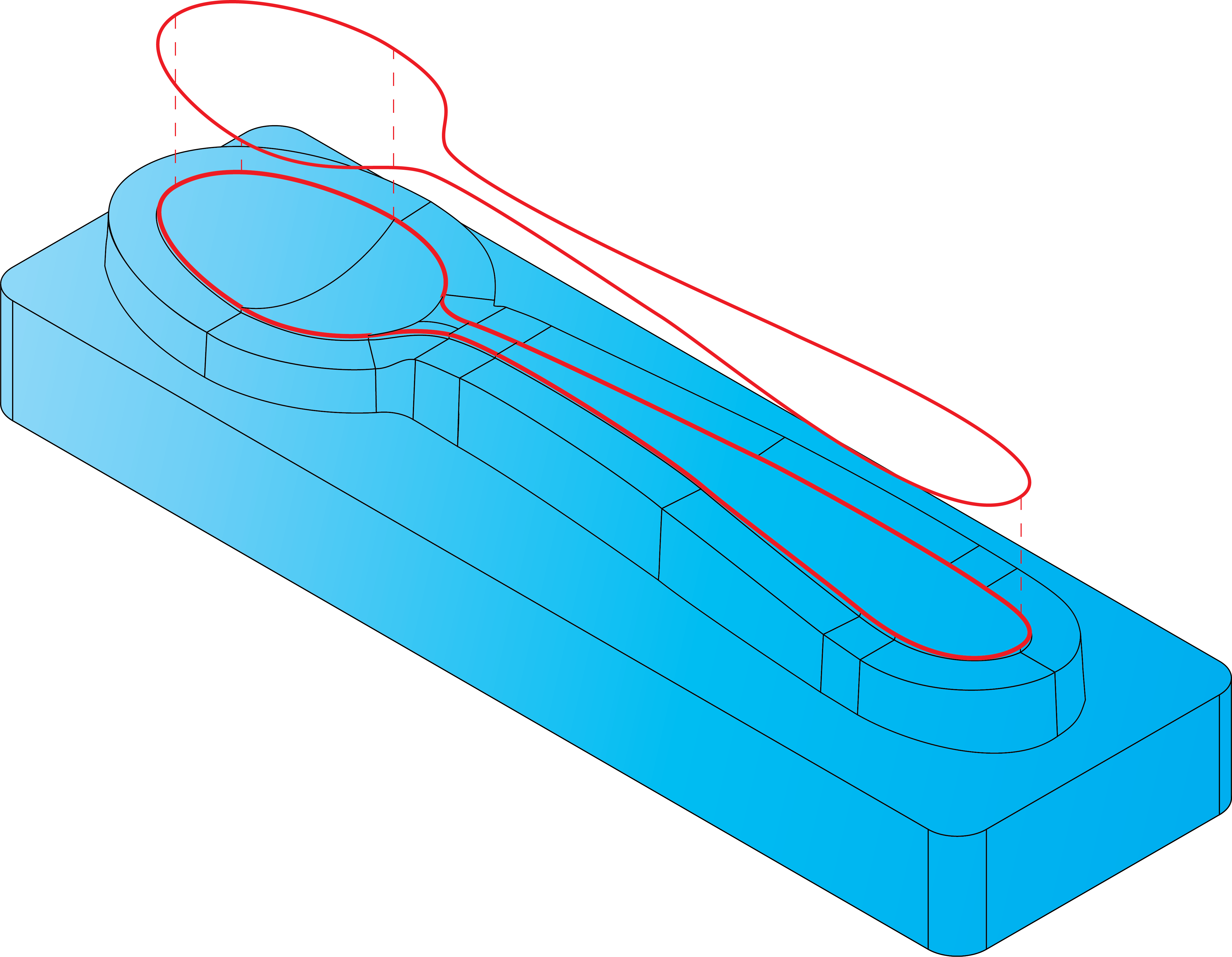
| Machining always takes place within a boundary or a set of boundaries. The boundaries define the limits of the tool tip motion. The area actually machined can be extended beyond the boundary by as much as the tool shaft radius. | 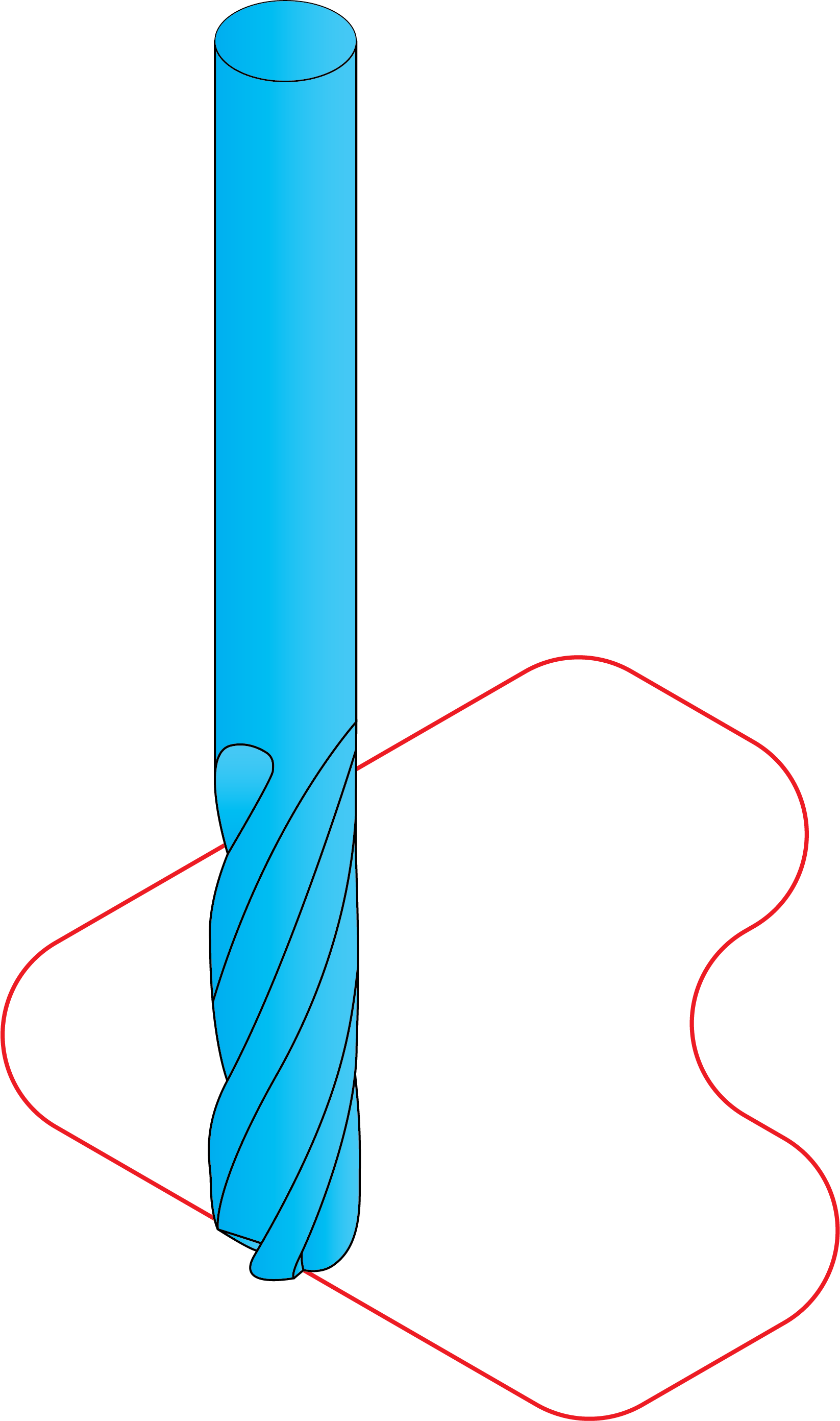 |
Boundary type
The following boundary types are available:
Created automatically
This option enables you to automatically create the boundary using the stock or target models.
Created manually
This option enables you to define a user-defined boundary based on a Working area geometry.
Boundary name
This section enables you to define a new boundary geometry or choose an already defined one from the list.
New
 displays the appropriate dialog box for the geometry definition.
Edit
 displays the Select
Chain dialog box enabling you to choose the chains for the boundary.
The chosen boundaries are displayed and highlighted in the graphic
window.
displays the Select
Chain dialog box enabling you to choose the chains for the boundary.
The chosen boundaries are displayed and highlighted in the graphic
window.
Boundary- Tool Relation
This option controls how the tool is positioned relative to the boundaries. This option is relevant only for 2D boundaries.
Projection direction
Projection direction enables the user to select the direction to project the tool path relative to the selected containment curve. You can choose the Projection direction from the following options:
Surface normal
Machining direction
User-defined
Same as drive curve sets the Projection direction as defined in the Advanced options of Drive curve.
Create additional cut from boundary
This option enables you to create an additional cut following the same shape as the boundary with specified Offset of additional cut.
Trim contours shorter than
This option enables you to exclude the contours of the tool path that are shorter than a specified length.
When this check box is selected, the contours whose length is smaller than the specified contour length value are excluded from the tool path. The specified contour length can be defined as percentage of tool diameter or as a value.