Multiaxis Machining Geometry
When the Technology is selected as Radial Roughing, the Geometry page allows you to define the following parameters:
When the Technology is selected as Wall Finishing, the Geometry page allows you to define the following parameters:
When the Technology is selected as Floor Finishing, the Geometry page allows you to define the following parameters:
Radial Roughing Strategy
The Strategy section enables you to define the strategy of the Multiaxis Machining. SolidCAM offers you the following strategies:
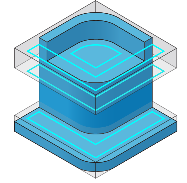
Offset
This strategy allows you to generate cuts that are parallel to the ceiling or floor geometry.
Adaptive
This strategy allows you to keep the cutting conditions constant. You can avoid full-width cuts by constantly measuring the engagement volume of the tool with material and gradually removing material off the remaining stock. This results in a stable load on the tool, which allows an increased material removal rate at higher feed rates, gradually reducing the overall machining time.
For the Offset and Adaptive strategies, you can select the following three sub-roughing strategies from the list:
|
 |
 |
|
|
Wall Finishing Strategy
The Strategy section enables you to define two types of strategies:
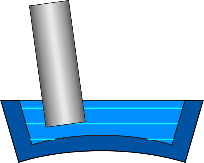
Morph between floor and ceiling
In this option, the tool path is created gradually by morphing between the floor surface and the ceiling surface.
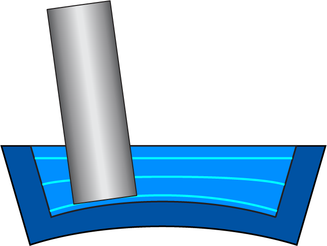
Parallel
In this option, the cuts generated are all offset cuts and are generated parallel to the wall. For this option, you can additionally select the required Guide curve as either the Floor curve or the Ceiling curve.
When you select the option of Floor curve from the list, the floor curve is automatically defined and cuts are created using this curve.
When the option of Ceiling curve is selected, the ceiling curve is automatically defined and cuts are created using this curve.
Floor Finishing Strategy
The Strategy section enables you to define two types of strategies.
Offset from wall
In this option, the cuts generated on the floor are all offset cuts from the wall.
Parallel
In this option, parallel machining cuts are generated on the floor of the part.
Machining surfaces
The Machining surfaces can be the entire model or any surface(s) of the design model.
![]() enables you to define a new
geometry for the operation with either selecting the Surfaces
enables you to define a new
geometry for the operation with either selecting the Surfaces
![]() that displays the Select
faces dialog box Or, by selecting Model
that displays the Select
faces dialog box Or, by selecting Model
![]() that displays the 3D Geometry dialog
box.
that displays the 3D Geometry dialog
box.
![]() enables you to edit an existing
geometry.
enables you to edit an existing
geometry.
![]() enables you to view the available
geometries on the model and choose the relevant one from the list.
enables you to view the available
geometries on the model and choose the relevant one from the list.
The Show button displays the Show geometry dialog box and the machining surfaces are displayed and highlighted in the SOLIDWORKSgraphic window.
Floor surfaces
| The Floor surfaces must
be defined using New
|
 |
Wall surfaces
| The Wall surfaces must
be defined using New
|
 |
Ceiling surfaces
| The Ceiling surfaces must
be defined using New
|
 |
|
The Ceiling surfaces can be defined only if the strategy of Offset from ceiling or Morph between floor and ceiling is selected. |
Stock to leave on
This option sets a clearance offset between the specified parts of the tool and the surfaces to be machined.
|
Negative value in Stock to leave on can be defined. This value cannot be bigger than the corner radius of the tool. This option is available only for the sections of Machining surfaces and Floor surfaces. |
Stock
Only when the Technology is selected as Radial Roughing, the Stock tab is available. This tab enables you to define the shape, size and orientation of the raw material to be machined around the machining surfaces.
Select the Respect stock model check box to update the stock 3D model.
Stock definition style
- The Auto updated stock option from the list, uses an STL model to define the raw material.
The Surfaces option, enables you to locally define stock by selecting the surfaces. This option must be used when you want to machine a pre-cast or pre-machined stock.
In the
Stock Surfaces section, selecting
![]() allows you to select new surfaces to
define the stock. Using
allows you to select new surfaces to
define the stock. Using ![]() you can edit the selected
surfaces.
you can edit the selected
surfaces. ![]() enables you to view
the available geometries on the model and choose the relevant one from
the list.The Show button displays
the surfaces selected for defining the stock.
enables you to view
the available geometries on the model and choose the relevant one from
the list.The Show button displays
the surfaces selected for defining the stock.
The Using 2D boundary option allows you to use a 2D curve form to define the stock. This option must be used to machine a limited area or an insert.
In the
Drive curve section, selecting
![]() allows you to select new 2D curves to
define the stock. Using
allows you to select new 2D curves to
define the stock. Using ![]() , you can edit the selected
curve. Using
, you can edit the selected
curve. Using ![]() , you can view
the available geometries on the model and choose the relevant one from
the list. The Show button displays
the curve selected for defining the stock.
, you can view
the available geometries on the model and choose the relevant one from
the list. The Show button displays
the curve selected for defining the stock.
Tolerance
This option allows you to set the tolerance value for the tool to deviate from the surface.
Shrink/Expand
The options of Shrink and Expand allow you to expand or shrink the stock model by the given value.
Stock has undercuts
This option enables the roughing strategy to identify any pre-machined areas or undercut areas in a stock. When this check box is not selected, the tool path is calculated for all of the stock resulting in a lot of air moves. When this check box is selected, stock slices take into consideration the undercut regions and the tool path is calculated accordingly resulting in time savings. |
 |
|
This option is not available when the option of Using 2D boundary is selected from the Stock definition list. |