Broaching
The geometry defined for this ToolBox Cycles strategy consists of several open chains, each chain is formed by one linear segment. During the geometry definition, SolidCAM checks its chains for suitability. If there are no suitable chains in the geometry, it is considered as not suitable for the sub-operation. When at least one suitable chain is found in the geometry, the geometry is considered as suitable for the sub-operation, the unsuitable chains are ignored during the tool path calculation.
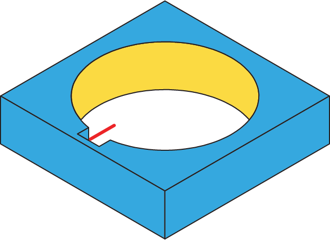
Geometry definition
A subset of open chains is used for this sub-operation.
Each such chain should consist of only one segment, and this segment should be linear. The direction of the chains is important for the Broaching sub-operation, it defines the cutting direction.
Technological parameters
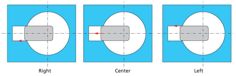
Tool side
This option enables you to define the tool location relative to the geometry.
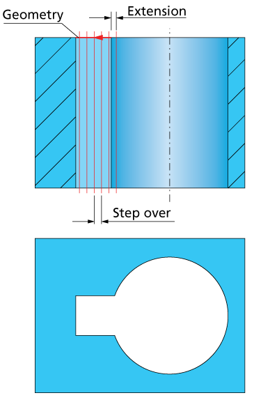
Extension
This option enables you to define the extension applied to the start point of the geometry. The machining will start at the position defined by this extension. The Extension distance is measured along the geometry chain line in the direction opposite to that of the geometry chain.
Step over
SolidCAM performs the broaching by a number of cuts parallel to the Z-axis. The first cut is performed at the distance defined by the Extension parameter. The distance between two successive cuts is defined by the Step over parameter.
In some cases the distance between the last cut and the previous cut is smaller than the distance defined by the Step over value. In such case, the Equal Step over option is available in order to obtain equally distributed cutting passes.
Retract
This option enables you to choose how the tool retracts from the material.
If the Constant option is chosen, the tool moves at each step by the distance specified in the Value edit box.
If the Outside the slot option is chosen, the tool retcract completely from the material at each step. The specified Value is the retract position that the tool should retract to at each step. This position is measured along the defined geometry as a tangent extension.
Tool path calculation
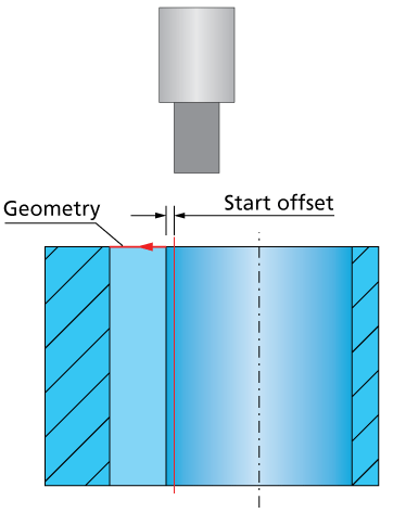
During the tool path calculation, SolidCAM tangentially extends the geometry chains at the distance defined by the Start offset parameter. The extension is performed according to the geometry chains direction.
At the next stage, the tool descends with the rapid feed to the Clearance level of the operation. At this level, the tool is oriented to be parallel to the machining geometry.
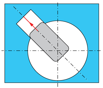
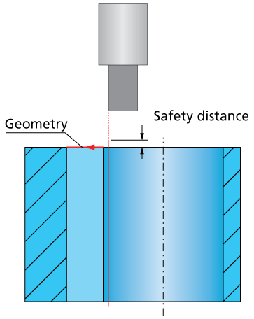
When the tool is rotated to the machining position, the tool is moved in such way that the tool tip will be coincident to the start point of the extended chain. Then the tool descends with the rapid feed to the Safety distance level. From this point, the tool performs the vertical cutting movement (along the Z-axis) with the cutting feed until the machining depth is reached.
After the cutting movement, the tool retracts vertically back to the operation Clearance level. The retract movement is performed with the rapid feed. At the Clearance level, the tool moved to the next cutting pass located at the Step over distance from the first one. The next cuts are performed in the same manner.