Levels page
This page enables you to specify the Z-levels at which the tool movements are executed. The default input values of these parameters are the CAM-Part values that you have specified in the CoordSys Data dialog box.
To define the Milling levels, enter the values or use the appropriate buttons or place the cursor in the edit box and pick the Z-levels on your 3D model.
Start level
This option defines the Z-level that can be optionally used for interoperational movements.
|
The Start level button and the related edit box are available only if the Operation Start level option is chosen in Part Settings. |
The default Start level value is equal to the Part Clearance level value of the Coordinate System chosen for the operation.
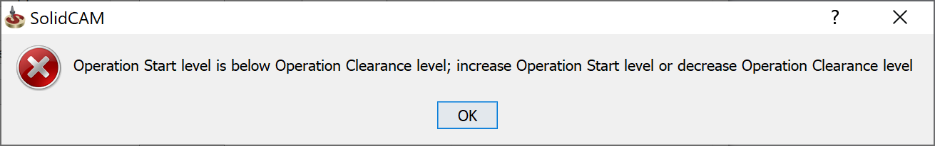
The Start level cannot be lower than the Operation Clearance level. If you are trying to save the operation in which the defined Start level is lower than the Operation Clearance level, the error message is displayed:
Clearance level
This option defines the Z-level to which the tool retreats when it moves from one cut to another.
Safety distance
This option defines the distance to the Upper level at which the tool starts moving at the Z feed rate you have entered for the tool. Movements from the Clearance level to this height are performed in the rapid mode.
Upper Level
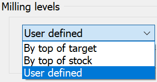
This option defines the Z-level at which the machining starts. You can select the Upper Milling level from the options- By top of target, By top of stock or User defined. When you select either By top of target or By top of stock the Upper level is populated automatically. By top of Target is chosen by default. If you enter a value in the Upper level field, the option automatically switches to User defined.
For the T-slot operation, the Upper level is the slot ceiling.
Milling Levels Constant/Variable
SolidCAM now supports the machining of geometries with different depths in a single operation.
Choosing Constant ![]() enables you to set the Upper
level, Lower level and
Step
down values.
enables you to set the Upper
level, Lower level and
Step
down values.
Choosing Variable ![]() displays the Variable levels button.
Clicking Variable levels displays
the Levels dialog box.
displays the Variable levels button.
Clicking Variable levels displays
the Levels dialog box.
|
The Variable levels option can help simplify the task of programming, especially when you want to use the same tool to perform the machining of many geometries having different depths. Such a task can now be achieved in just one operation. |
Lower level (Depth)
This option defines the Z-level below which the tool does not mill in any milling strategy.
Delta
This option defines the offset for the cutting depth that can be changed with its associativity preserved. This parameter is always relative to the Depth defined for the operation.
If the Delta depth value is positive, a blue arrow is displayed near its field indicating a positive offset value (in the positive direction of the Z-axis).
![]()
If the Delta depth value is negative, a red arrow is displayed near its field indicating a negative offset value (in the negative direction of the Z-axis).
![]()
The following operation parameters are associative to the SOLIDWORKS model.
Clearance level
Upper Level
Lower Level
SolidCAM enables you to define these parameters by picking entities on the solid model.
|
The Depth parameter used in some operations (Profile, Pocket, etc.) is indirectly associative. You have two possibilities:
More... |
Related Topics