Save Updated Stock to STL
This option enables you to define a new CAM-Part based on some other pre-machined CAM-Part, using the result of machining of the pre-machined part for the Stock model definition. Machining of a part can thus be performed in several stages, with one CAM-Part for each stage, by passing the machining results from one stage to the next through an Updated stock model obtained after the last operation of each CAM-Part and saved in the STL format.
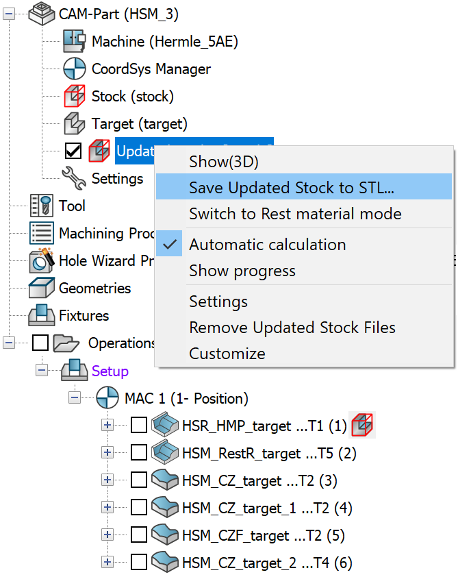
Right-click the Updated stock subheader in CAM Manager tree and choose the Save Updated Stock to STL command from the menu.
2. The Save Updated Stock to STL dialog box is displayed.
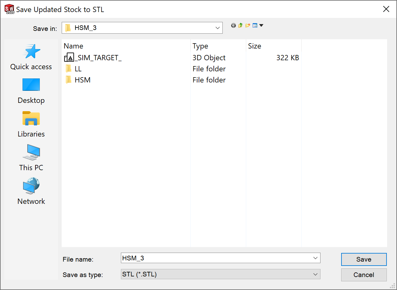
3. Define the name and location for your file. The default name of the
Updated stock model STL file is inherited from the CAM-Part name. The
default location of the STL file is the CAM-Part folder for non-compressed
CAM-Parts (*.prt). For compressed CAM-Parts (*.prz), the default location
is that of the compressed CAM-Part files.
4. Click Save.
5. The Facet Model Transform Utility dialog box is displayed.
![]()
6. Click OK to save the updated stock as *.STL or *.FCT file in the new transformed position with the bodies that you have selected.
Loading the Updated Stock STL
1. To load the *.STL or *.FCT file, open the SOLIDWORKS assembly.
2. Add a New Milling Part.
3. Define the Coordinate System.
4. Click Stock to load the Stock dialog box.
5. In the Defined by section choose STL in the drop-down list.
6. In the STL
File section, browse the STL file and click ![]() .
.
7. The result of machining of the previous CAM-Part gets loaded as a new CAM-Part.
8. You can now proceed with defining the Operations in the CAM Manager as usual.
Editor for Updated Stock STL
This feature is useful for multi-fixture parts where we need to rotate the stock around or duplicate them to be used in another CAM-Part with different fixturing.
STL editor supports
- Shifting of bodies
- Rotation of bodies
- Scaling of bodies
- Deleting of bodies
- Copying of bodies
- Merging multiple STL files
- Saving to separate files
- Saving based on CoordSys
Facet Model Transform Utility dialog box can be launched for editing any STL or Facet Model in SolidCAM.
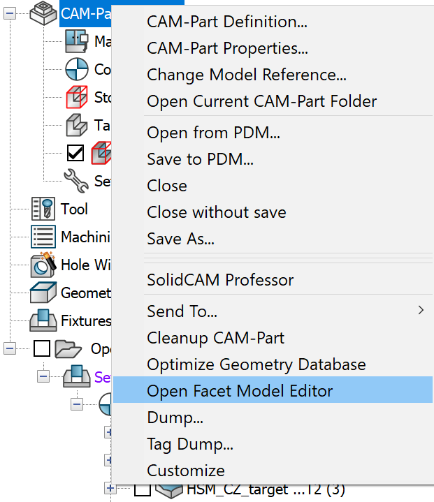
1. Right-click the CAM-Part and choose Open Facet Model Editor from the menu to edit any STL or Facet model.
![]()
2. Click Open and browse the STL file or Drag & Drop the STL file into the utility window.
3. After manipulating the required data, click Save As to save the updated stock as *.STL or *.FCT file.
Bodies
The bodies are designated as Solid and Group. Solids are numbered from 1, 2 and so on. Each solid is identified by a different color. Clicking on the row in the Bodies section highlights the Part in Red color in the Simulation window. You can Delete, Copy and Name the bodies using the respective buttons. Select the row and click Name. The following dialog box is displayed.
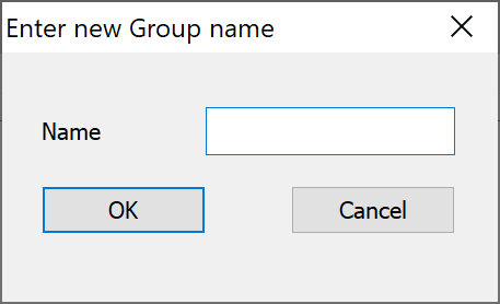
Enter the new name for the Group and click OK.
Rotate
Select the solid body and rotate it in the X, Y and Z direction using Rotate X, Rotate Y and Rotate Z buttons.
Shift
You can shift the solid body in the X, Y and Z direction using Shift X, Shift Y and Shift Z buttons.
Scale
The default Scale is set to 1. Enter a value for the scale factor and click Scale.
Save options
You can save the updated stock model as either an *.STL file or *.FCT file. There is also an option to save based on other Coordinate systems in your CAM-Part. All MAC positions are displayed. The Output Coordsys can output to any of them.
The default output Coordinate system is the CAD system. This is useful when we are taking the updated stock from one CAM-Part to another CAM-Part where we have the same model in SOLIDWORKS. This will position the STL when you use in the Stock by STL. In your second CAM-Part it will be located in the right position.
If your original SOLIDWORKS model is going to be setup in a different assembly or different fixture you may have to choose one of the Coordinate systems from the drop-down list or you may have to modify the Shifts and Rotations.
|
When launched within a CAM-Part, the MAC positions from that CAM-Part are displayed. You can have additional MAC positions setup to help you locate or edit an STL that you would like to shift or move around. |
Show All CoordSys – This option displays the CAD, CAM and the MAC positions.
Save groups to separate files – This option saves the groups as separate STL files.
Commands -Displays the list of commands executed.
Run Commands - Runs all the commands executed at a time.
Drag and Drop existing STL or FCT files
The Facet Model Editor also supports Drag & Drop existing STL or FCT files into the utility window for opening / editing. This can be useful for Save as Updated stock or when using the Facet Model Editor by itself.
When you drag an STL file into the utility window it will bring it into the editor as its own item. If you drag multiple STL’s in, you will get an option to merge the file. If you merge the file all the bodies will be brought in the Editor and you can Shift, Rotate etc. these STL bodies.