Defining the translational axis
When all the non-moving components of the CNC-Machine are defined, you have to define the moving components. Moving components have to be defined according to their hierarchical “parents-children” dependencies. The order of the definition is the following: “parents” have to be defined before the “children”. In case of Table-Table machines, the first component to be defined is the sliding carriage that performs the X-axis movements and then the spindle unit that moves along the Z-axis. These two components are joined into a separate set; the movements of this set are independent from the movements of Y-, B- and C-axes.
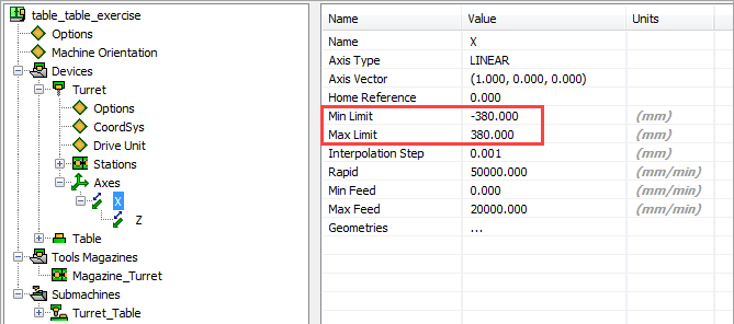
Click the X item in the CNC-Machine definition tree. In the element properties table, the orientation of the axis is defined by a vector with three coordinates. The following limits are set for the axis: the Min Limit value is -380 and the Max Limit value is 380.
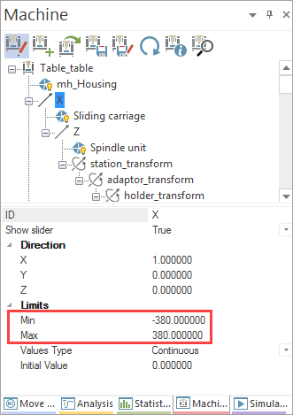
Take a note that the same values must be set in the corresponding VMID file.
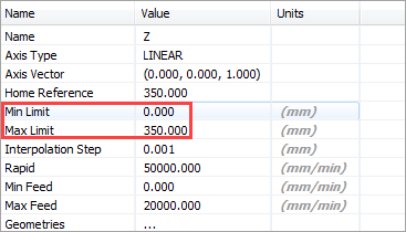
Click the Z item. Notice that the Z-axis is a “child” of the X-axis. The following limits are set for the Z-axis: the Min Limit value is 0 and the Max Limit value is 350.
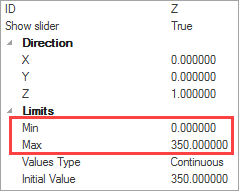
Take a note that the same values must be set in the corresponding VMID file.
|
Use the sliders of the Axis Control tab to check the translational movements of the defined geometry along the axis. |
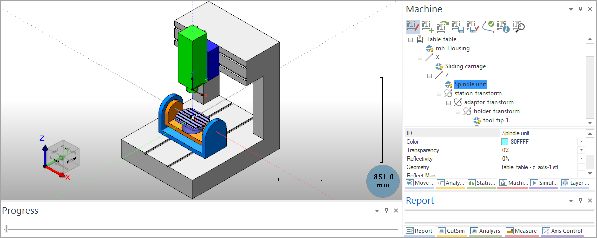
Clicking the Spindle unit item highlights the spindle and displays the component properties.
During mouse rotation in machine simulation, a dot is displayed to show end-users the selected rotation center point.
Click the Y item in the CNC-Machine definition tree. In the element properties table, the orientation of the axis is defined by a vector with three coordinates.
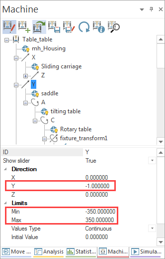
In this case, the defined translational axis is the Y-axis. Notice that the direction is defined according to the tool movements along the axis. The tool movement in the positive Y-axis direction causes the saddle movement in the negative Y-direction.
![]()
Therefore, the direction is defined with the following values: 0.00000 -1.00000 0.00000. This vector defines the direction of the CNC component movement when the tool moves in the positive axis direction.
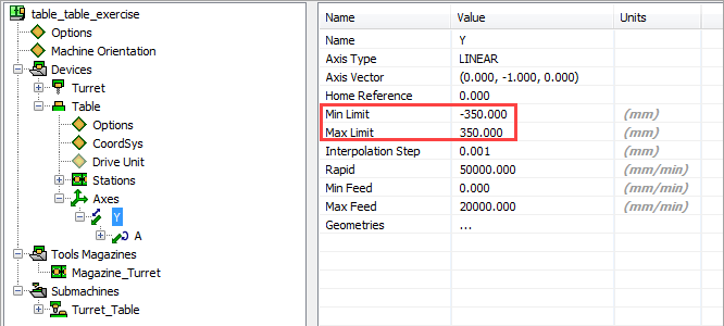
The saddle performs the Y-axis movements within the range of the minimal and maximal limit values. The Min Limit value is set to -350 and the Max Limit value is set to 350.
Take a note that the same values must be set in the VMID file.
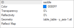
After the translational axis parameters, the geometry of the part performing the translational movement along the axis is defined. In this case, this part is the saddle.
|
Use the sliders of the Axis Control tab to check the translational movements of the defined geometry along the axis. |
Related Topics