Face Milling Geometry
This page enables you to define the machining geometry for the operation.
The geometry for Face Milling operations is defined using the Face Milling Geometry dialog box.
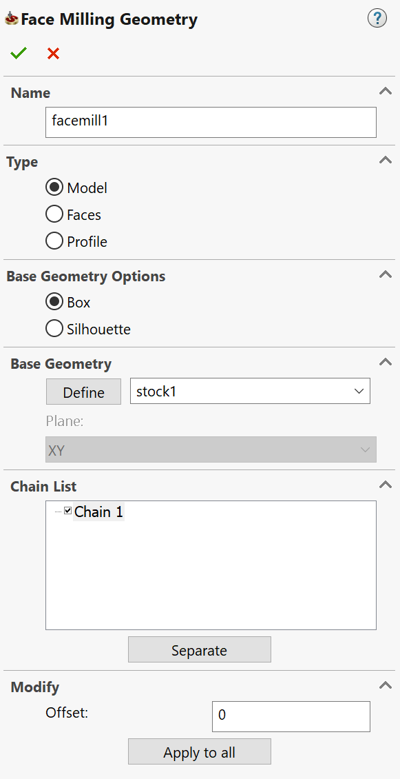
Name
This edit box enables you to define the geometry name.
Type
This section enables you to choose the method of the Face Milling geometry definition.
|
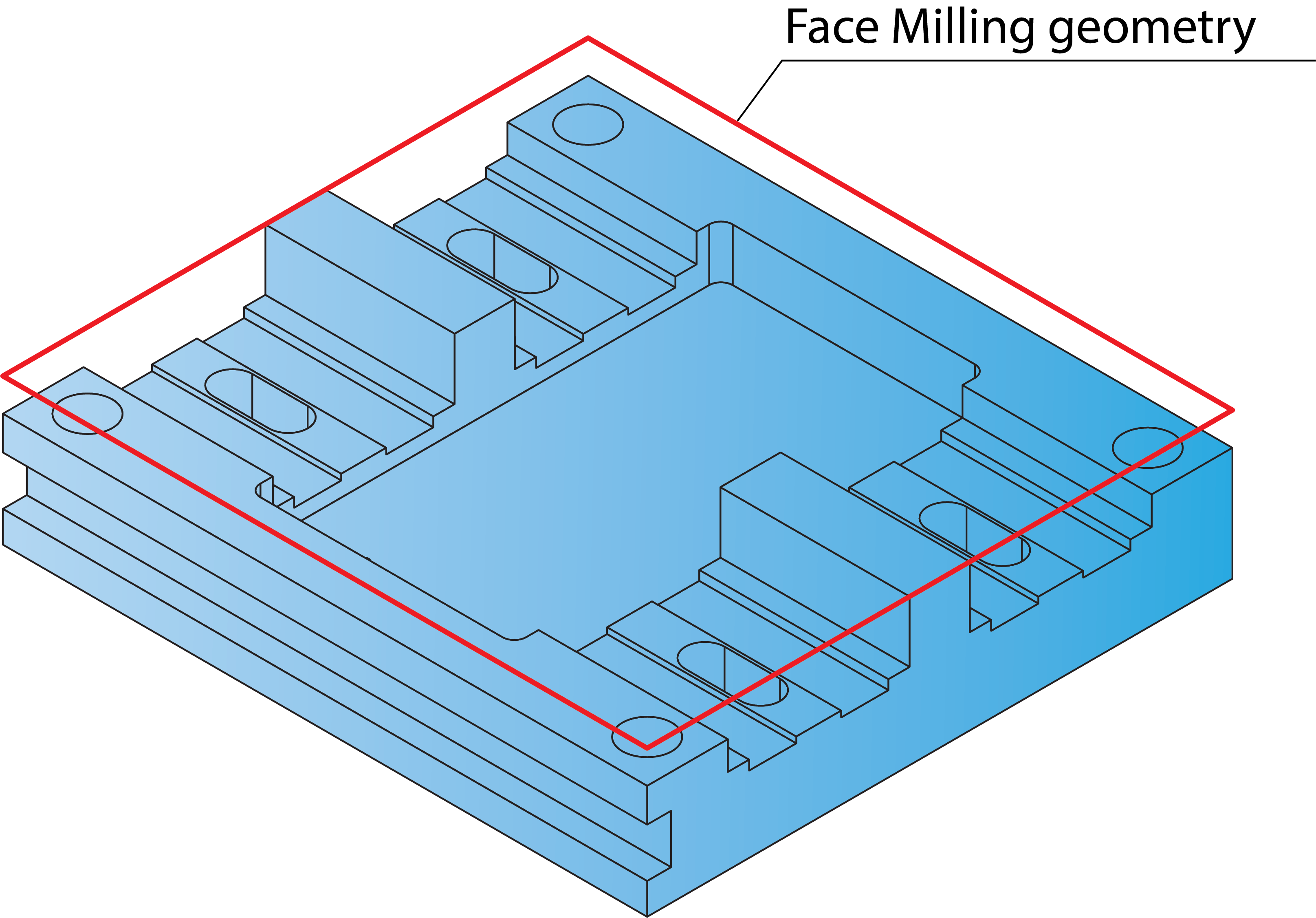
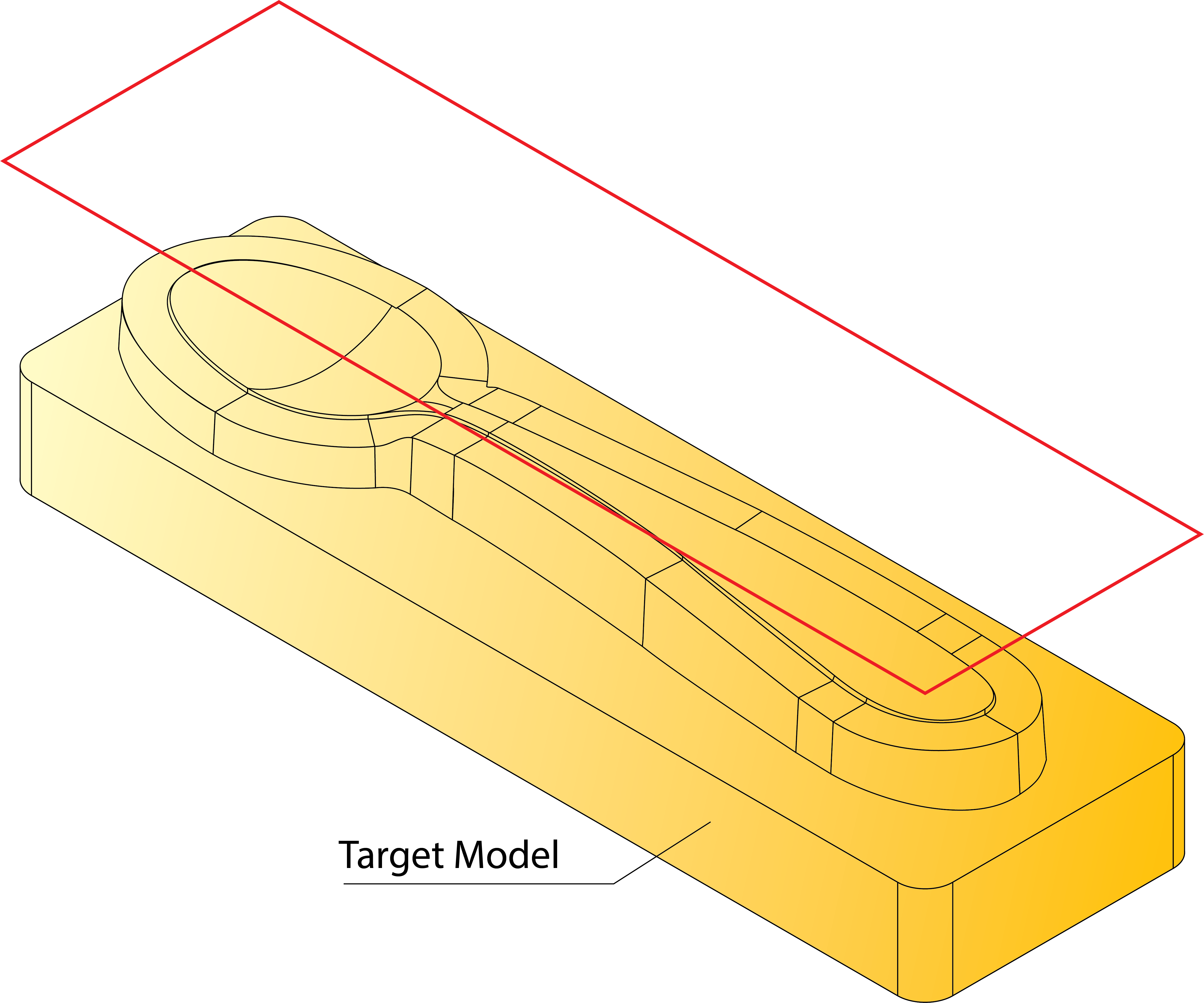
This option generates a rectangular box in the XY-plane surrounding the Target model and selects it for the Face Milling geometry. The geometry chain is displayed in the Chain List section. Upon adding a Face Milling operation, if the Target model is defined in the CAM-Part, the geometry definition is automatically generated using this method and is made the default selection on the Geometry page.
|
 |
|
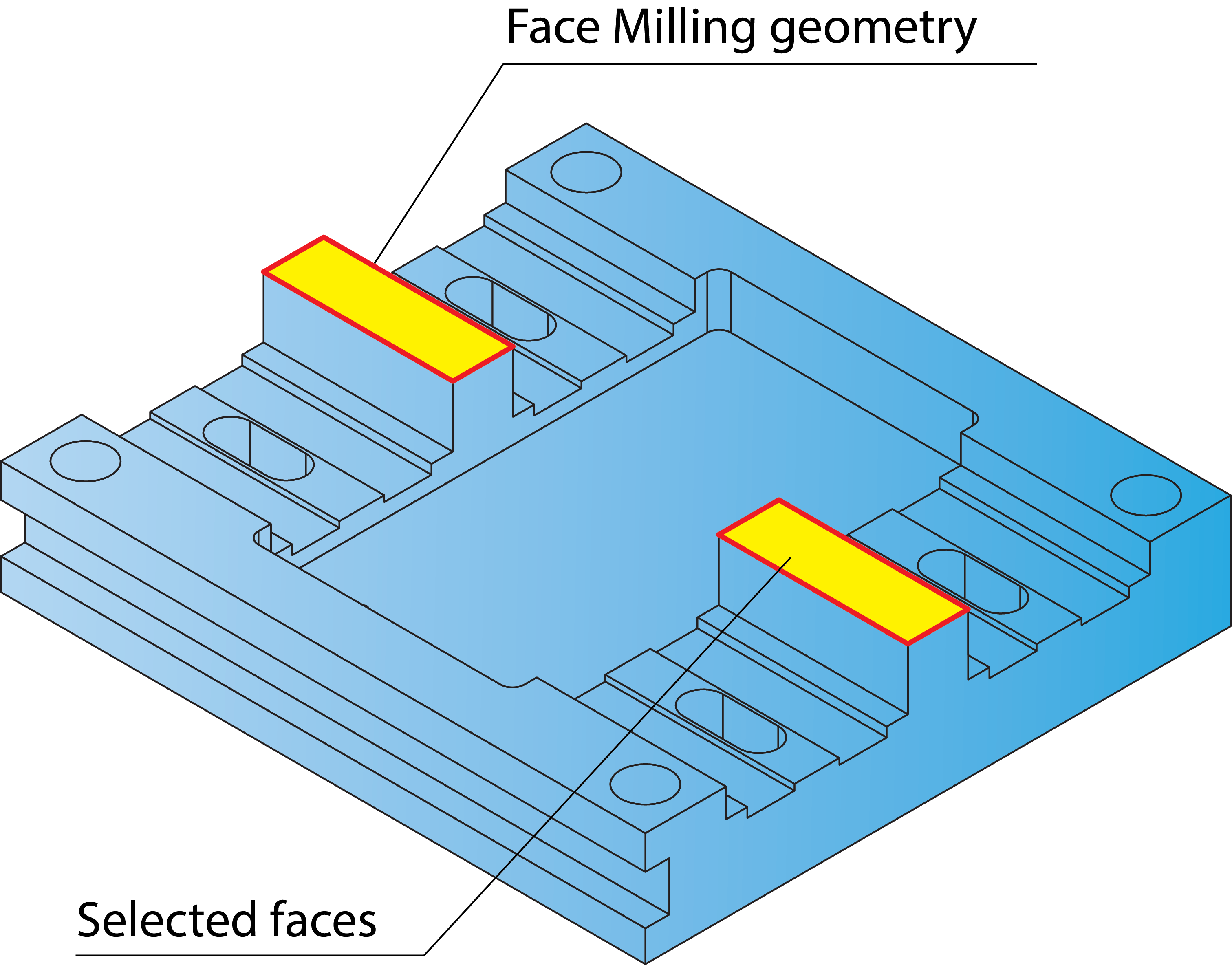
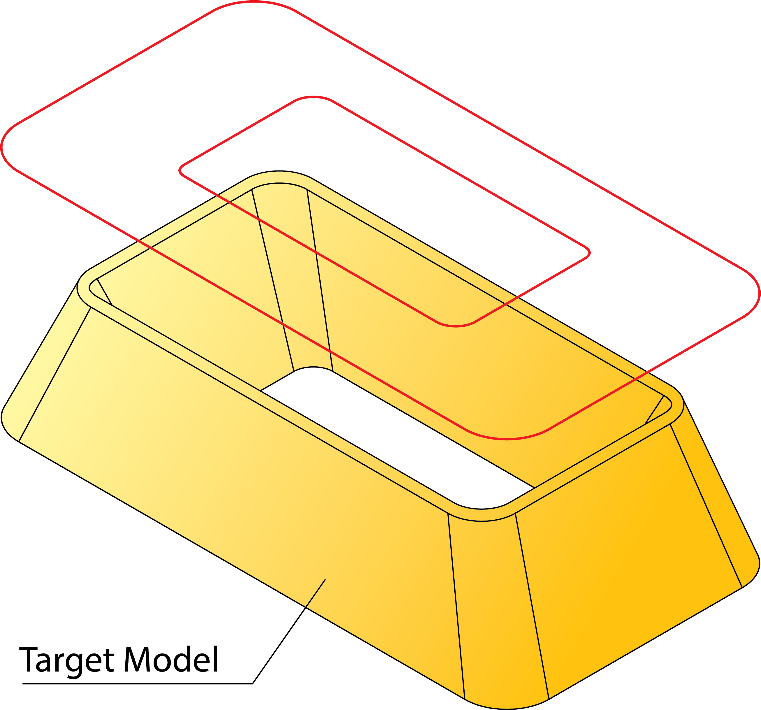
This option enables you to define the Face Milling geometry by face selection. The Define button and related combo-box enable you either to define a new faces geometry with the Select Faces dialog box or to choose an already defined geometry from the list. When the model faces are selected, SolidCAM generates a number of chains surrounding the selected faces. These chains are displayed in the Chain List section. |
 |
|
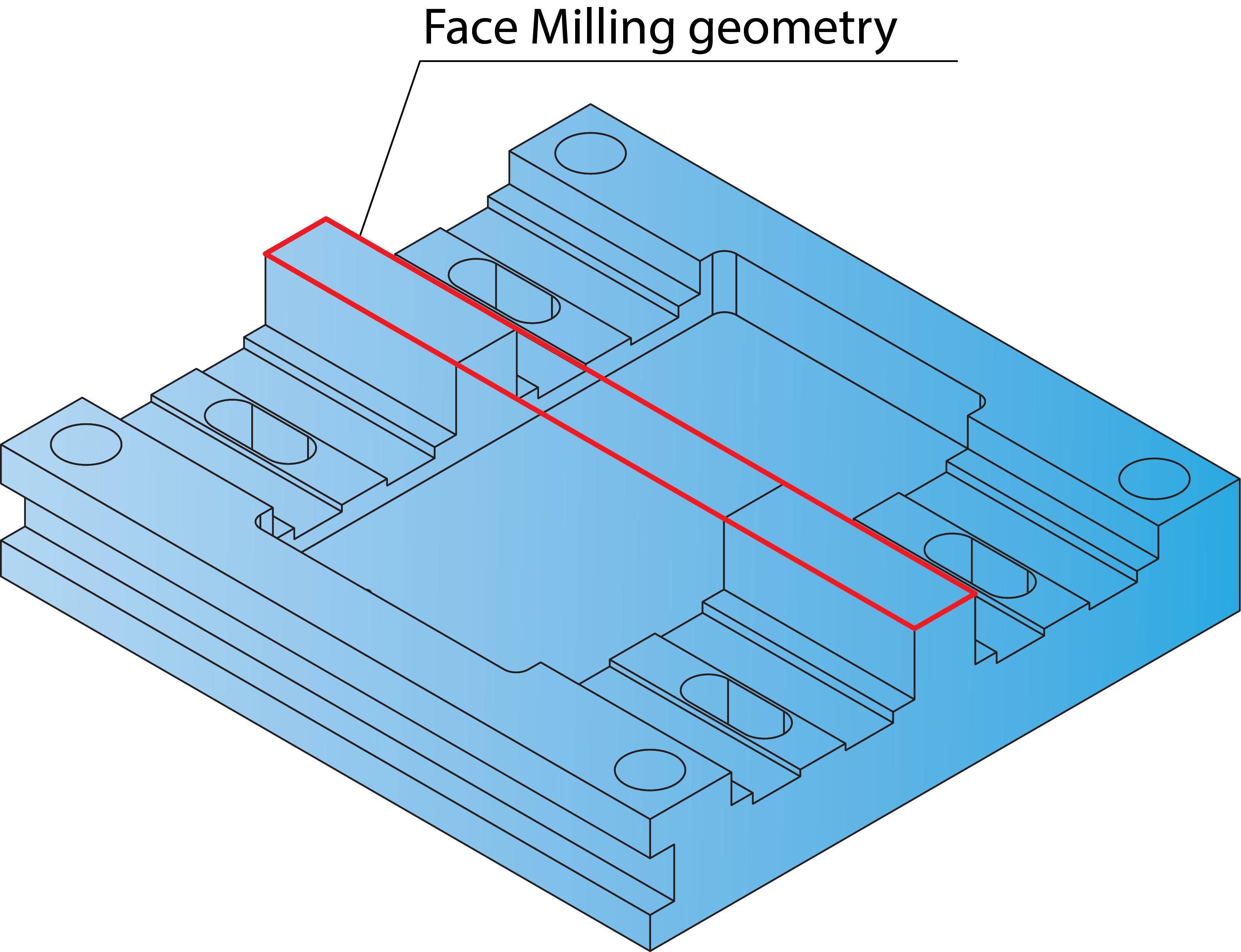
This option enables you to define the Face Milling geometry by selecting a chain. The Define button and related combo-box enable you either to define a new profile geometry with the Geometry Edit dialog box or to choose an already defined geometry from the list. The defined chains are displayed in the Chain List section. |
 |
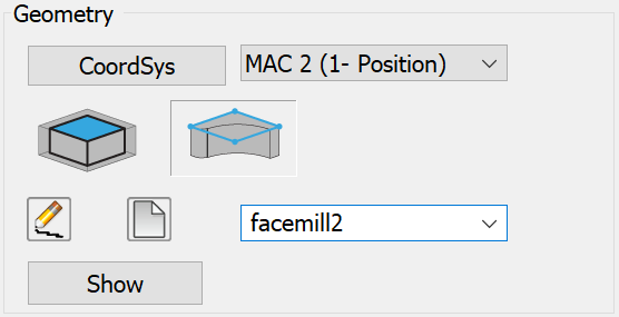
Base Geometry options
This option automatically generates a rectangular box surrounding the selected model. The tool path is limited to the area contained in this box.
This option automatically generates a silhouette boundary of the selected model/face. A silhouette boundary is a projection of the outer and inner contours of the selected model onto the XY-plane.
|
This section is available only for Model/Faces options chosen in the Type section. |
Chain List
This section displays all the chains chosen for the Face Milling geometry.
Each chain entry in the list contains a check box. By clearing this check box, you can exclude the corresponding chain from the defined geometry.
The right-click menu is available on the chain entries in the list.
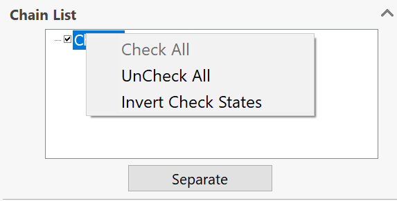
The Check All command selects all of the chain check boxes; all the geometry chains will participate in the current geometry.
The Uncheck All command removes the selection from all of the chain check boxes; all the geometry chains will be excluded from the current geometry.
|
When the selection
is removed from all of the chains in the list, the |
The Invert Check Status command enables you to invert the selection status for all the chain entries; all the selected check boxes will be unselected and vice versa, all the unselected check boxes will be selected.
The Merge button enables you to merge all the Face Milling geometry chains into a single chain. The Separate button enables you to divide a merged chain into its initial separate chains.

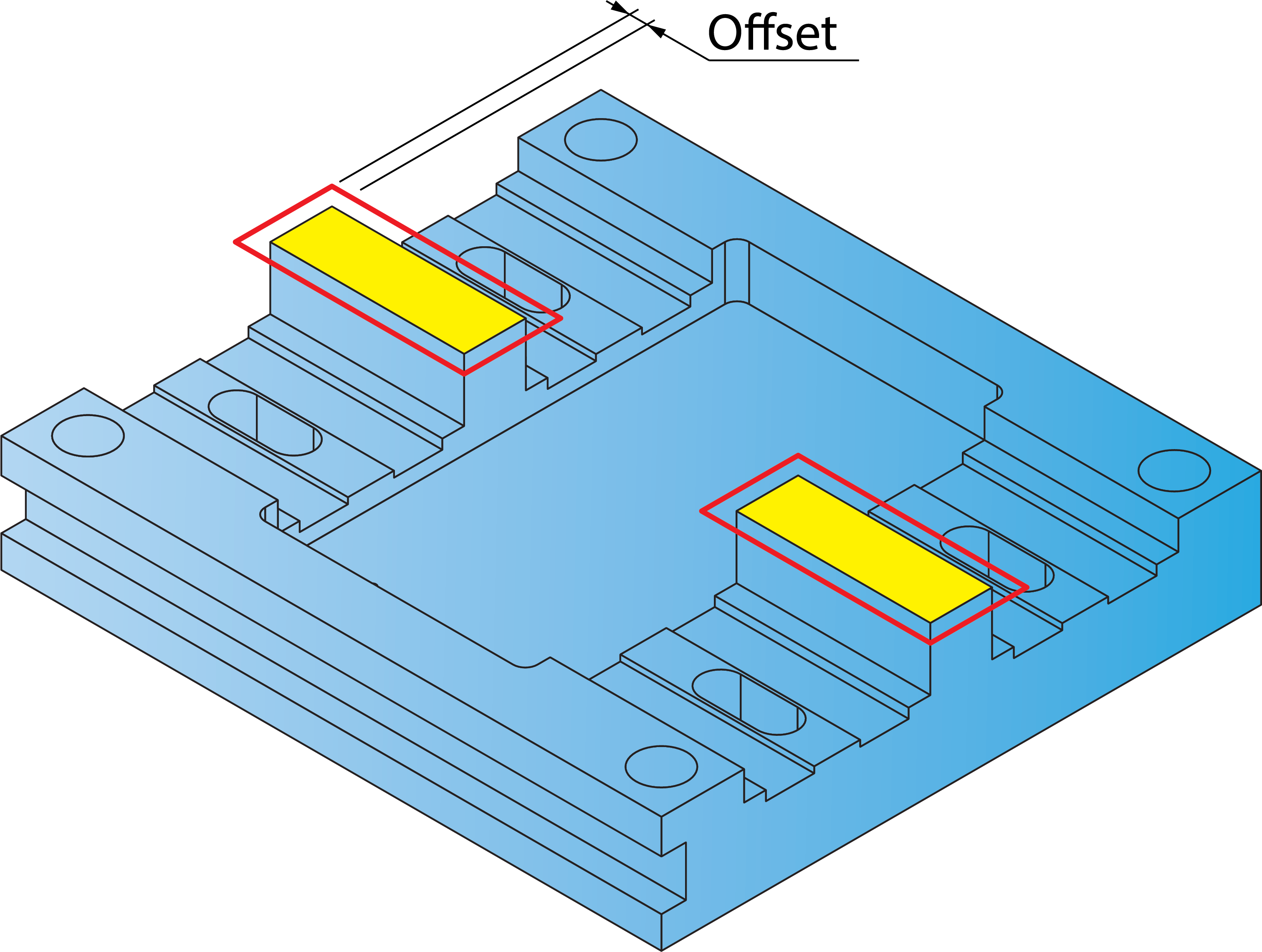
Modify
This section enables you to offset the chain currently selected in the Chain List section. The Apply to all button enables you to apply the specified offset value to all the chains.
Related Topics