Flattened surface on cylinder
This ToolBox Cycles strategy enables you to perform the machining of the flattened surface on cylinder.
Geometry definition
The strategy provided by this sub-operation can be performed only on open chains, each chain consisting of one linear entity; accordingly, the geometry should contain at least one open chain. The geometry containing only closed chains is considered as unsuitable. The geometry containing at least one open chain is considered as suitable. The mixed geometry containing a number of open and closed chains is considered as suitable, but all the closed chains are ignored during the tool path calculation.
SolidCAM checks the entities of all the open chains of the geometry for suitability of a specific chain for the sub-operation. The chain accepted as suitable for this sub-operation should consist of one linear entity only. Therefore, the geometry to be accepted for the sub-operation should contain at least one such chain. All the chains consisting of more than one entity or chains with a single non-linear entity are ignored during the tool path calculation.
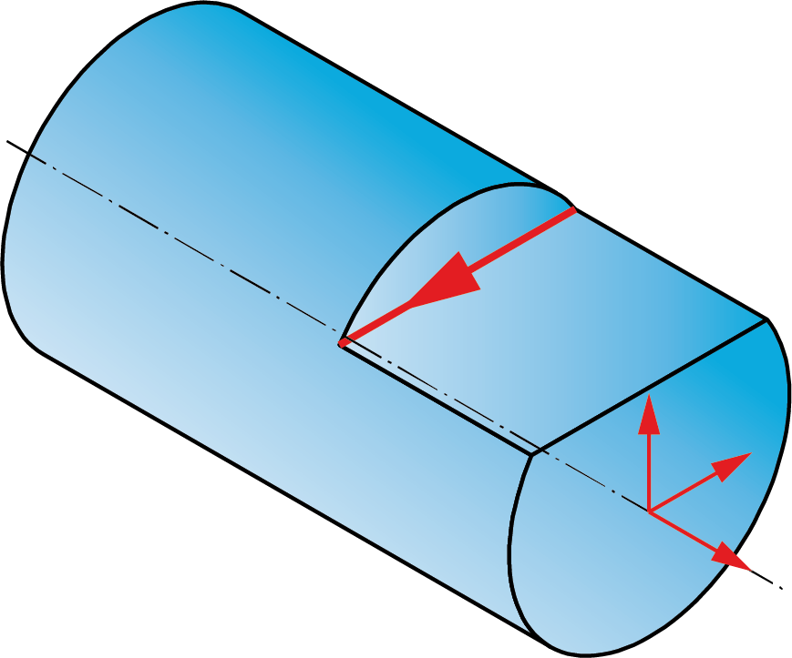
Before the geometry definition, the coordinate system should be defined with the origin located at the cylinder revolution axis. The Z-axis of this coordinate system should be normal to the floor of the flattened surface. The X- and Y-axis orientation does not affect the tool path. This coordinate system should be used for the geometry definition.

A number of chains composed from single linear entities should be selected.
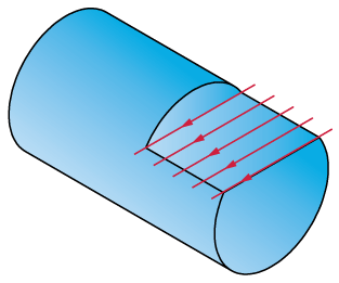
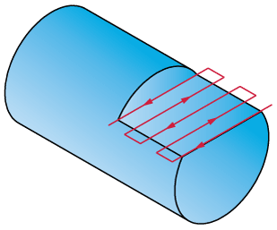
Generally, the ideal shape of the chain is a line (based on a model edge or a sketch entity) perpendicular to the revolution axis of the cylinder.
The machining of the linear chain not perpendicular to the revolution axis of the cylinder will cause errors in the tool path.
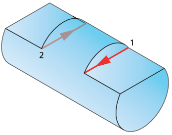
The direction of the chain is important; it will be used to determine the direction of the machining.
Technological parameters
Rough
SolidCAM enables you to perform the flattened surface machining in a number of cutting passes distributed along the tool axis.
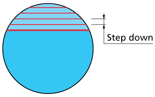
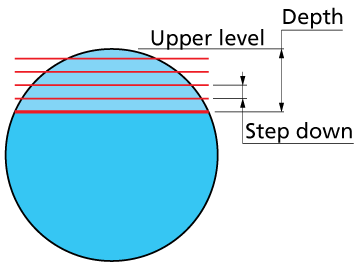
Step down
The distance between two successive cutting levels is defined by the Step down parameter. The Equal step down option enables you to define a number of evenly distributed cutting levels. SolidCAM automatically calculates the actual step down to keep an equal distance between all passes, while taking into account the specified Max. Step down value so that it is not exceeded.
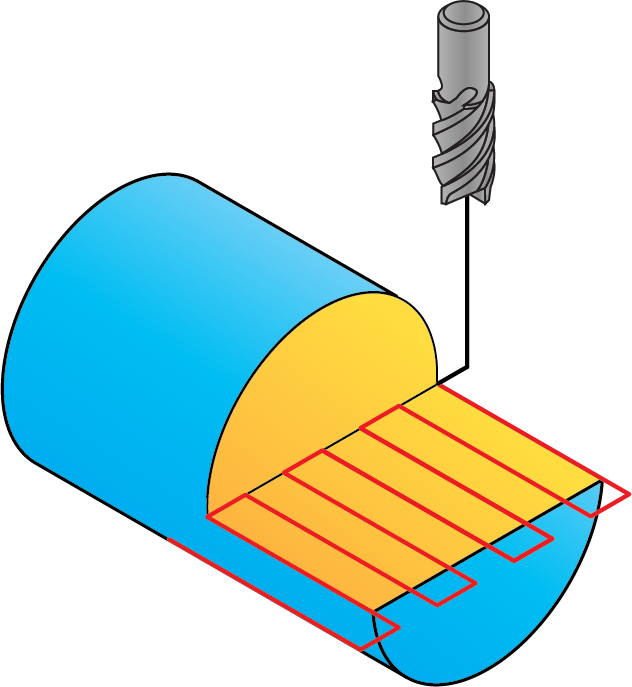
Cutting direction
This section enables you to define the tool path direction relative to the geometry.
When the Across option is chosen, the tool path is generated across the geometry chain.
|
 |
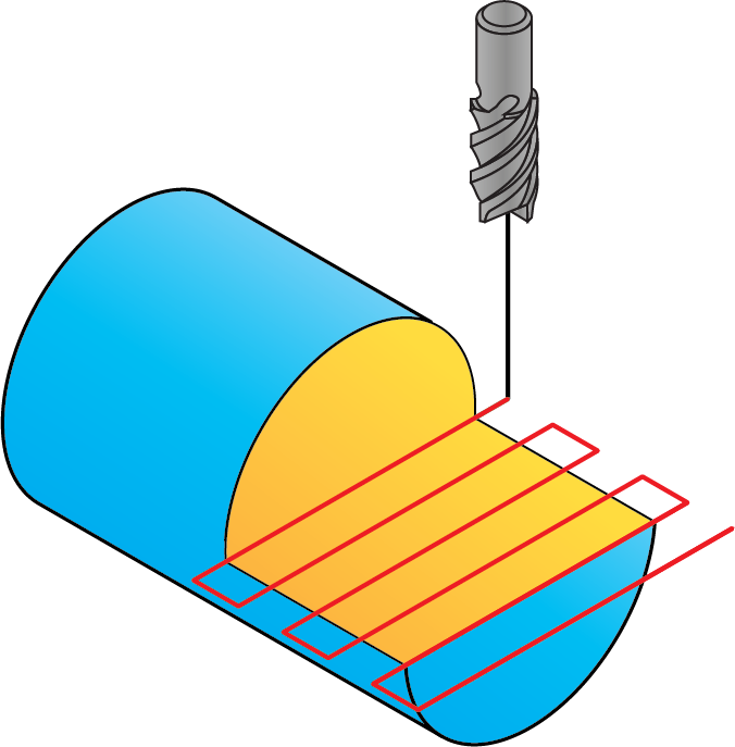
When the Along option is chosen, the tool path is generated along the geometry chain.
|
 |
Clear offset
This option enables you to perform the machining in a number of equidistant cutting passes parallel to the geometry and distributed in the XY-plane. The machining starts at a specific Z-level from a distance from the geometry defined with the Clear offset parameter and continues in a number of equidistant cutting passes. The distance between two successive cutting passes is defined by the Step over parameter.
![]()
Direction
This section enables you to define the direction of the Clear offset passes.
When the One way option is chosen, all the cutting passes are generated in one direction, maintaining the climb milling for all the cuts.
In this mode the cutting passes located at the same Z-level are not connected, the tool path linking is performed through the Clearance level.
When the Zigzag option is chosen, the tool path is generated in the zigzag manner, the direction is changed for each two successive cutting passes. The first Clear offset cutting pass (closest to the geometry) is performed maintaining the climb direction; the direction of all the odd cutting passes is the same. The direction of even cutting passes is reversed (conventional).
In this mode the cutting passes located at the same Z-level are connected as follows: when a specific cutting pass is machined, the tool directly moves to the start position of the next successive cutting pass.
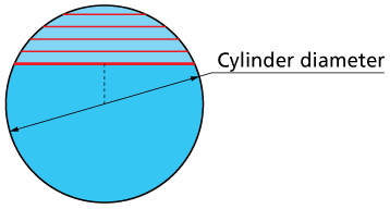
Cylinder diameter
This parameter enables you to define the diameter of the cylinder.
Clicking Preview
(![]() ) enables to toggle between
showing and hiding the cylinder circumference on the solid model.
) enables to toggle between
showing and hiding the cylinder circumference on the solid model.
Offsets
This section enables you to define Wall and Floor offsets for this sub-operation. The Wall offset is applied to the wall adjacent to the flattened surface; the specified offset is left unmachined during the current sub-operation. The Floor offset is applied to the floor of the flattened surface; the specified offset is left unmachined during the current sub-operation. When the Floor offset value is specified, SolidCAM performs the machining by the Z-levels defined with the Step down parameter. The machining is performed until the Floor offset level.
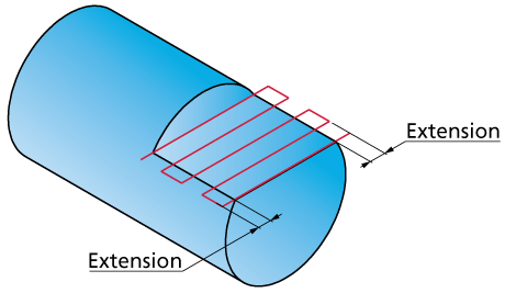
Extension
During the machining, the tool path is extended over the edges of the flattened surface in order to exit from the material at each cutting pass. The Extension section enables you to define the tool path extension either by percentage of the tool diameter (the % of tool diameter option) or by value (the Value option).
Finish
The Wall finish option enables you to perform a final finishing pass cleaning the walls. You can specify the Step down value in a separate field.
The Floor finish option enables you to perform a final finishing cut cleaning the floor.
Tool path calculation
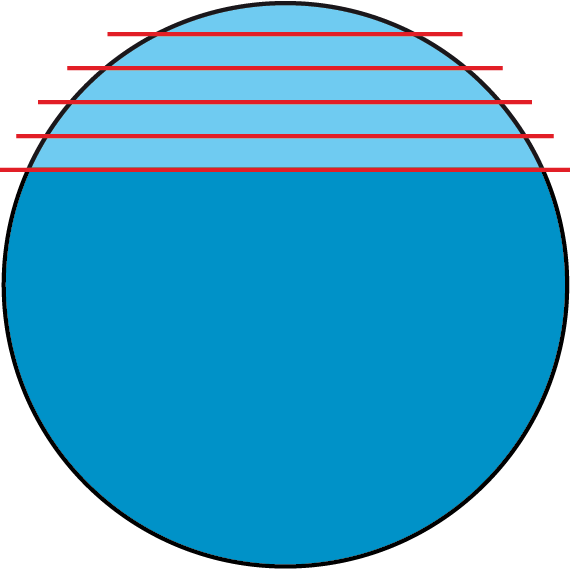
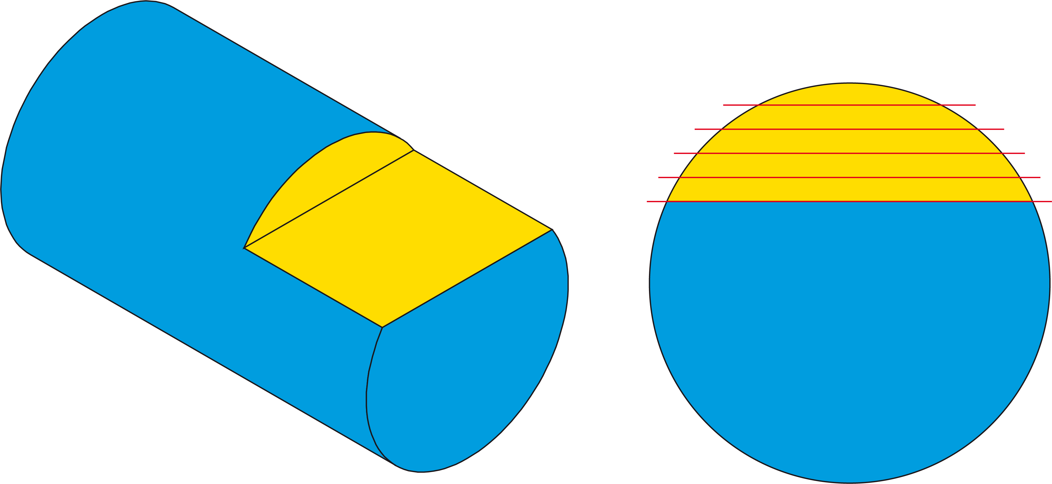
In the beginning of the tool path calculation, SolidCAM generates a number of cuts retracing the initial chain and located on a number of Z-levels. These Z-levels are distributed between the Upper level and the Depth level (modified with the Floor offset) of the operation; the distance between two successive cutting passes is defined with the Step down parameter.
At the next stage SolidCAM determines the cylinder section circle that will be used for the tool path trimming. The circle diameter is defined by the Cylinder diameter parameter, the center is defined as the projection of the middle point of the linear chain onto the XY-plane of the current Coordinate System.
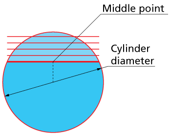
The cutting passes are trimmed with the generated circle.