Simulation Menu
Simulation Menu has the following tabs:
Simulation
Control
Simulation
Run Speed
Views
Visibility

Simulation
The simulation tab provides you with a number
of toolbars enabling you to control the simulation process and the model
visualization in the graphic area. The arrow near each toolbar enables
you to customize this toolbar by displaying or hiding certain buttons.
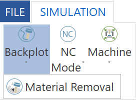
The Simulation tab provides you the following
simulation buttons:
|
Backplot enables you to see
the tool path visible without material removal at this stage.
Material Removal
enables you to see only material removal, no tool path is visible
at this stage. |
|
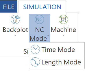
NC Mode enables you to use the
NC code positions from the move list. In this mode, the machine
motion jumps from one position to the next.
Time
Mode enables you to see the machine simulation with real
time feed rate motions.
Length Mode simulates the machining
process with a constant speed, distance, and time regardless of
the feed rate. This mode allows you to jump the simulation to
any position along the simulation. The tool jumps to a specific
tool path distance and collisions are not verified over the skipped
distance. |
|
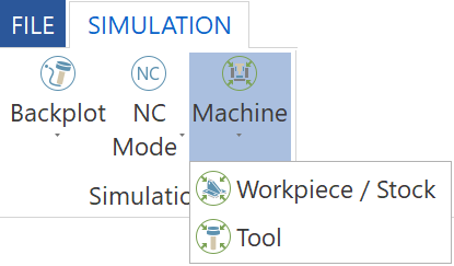
Workpiece/
Stock - In this option, only tool and workpiece are visible.
The workpiece is stationary, and the tool moves around the workpiece.
Machine - In this option machine
and workpiece are visible. The machine is stationary, and workpiece
is mounted on the table.
Tool - In this option, only
tool and workpiece are visible. The tool is stationary, and workpiece
moves around the tool. |
Control
The
Simulation tab also provides you the following control buttons:
|
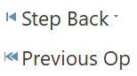
Step Back allows you to step
through the tool path to the previous single tool path segment.
Prev Feed Move returns
the simulation back to the previous feed move in the tool path.
Previous Op allows you to navigate
to the previous operation. When you select this
button, the collision checking and other algorithm checking algorithm
is disabled. This function only allows you to reach quickly to
the position that you want to check in detail. |
|
Run
- Starts the simulation.
Loop Run - This option starts
the simulation again once it is over.
Feed Move Run - This option
schedules feed moves with the set speed. Rapid moves are fully
simulated without displaying them. |

|
Stop
- Stops the simulation. |

|
Fast Forward - Starts the simulation
from the selected step and goes to the last position from last
operation without showing the simulation process on the simulation
window. If any collision takes place during this operation,
then this collision is reported. |
|
Step
Fwd - This option allows you to step through the tool path
to the next single tool path segment.
Next Feed Move - This option
advances the simulation to the next feed move in the tool path.
Next Op - This option allows
you to navigate to the next operation. When you select this, the
collision checking and other algorithm checking algorithm is disabled.
This function only allows you to reach quickly to the position
that you want to check in detail. |
|
Restart
- Starts the machining over again from the beginning. |
Simulation Run Speed
|

|
This
control bar allows you to run the simulation faster/slower or
to show simulation with some steps on the display screen. |
Views
The
Simulation tab also provides you the following buttons responsible for
the display of the simulation model:

|
Fit
enables you to adjust the simulation model size to the graphic
area.
|

|
Isometric enables you to rotate
the simulation model into the isometric
view.
|

|
Top enables you to rotate the
simulation model into the top side view.
|

|
Front
enables you to rotate the simulation model into the front.
|

|
Right enables you to rotate
the simulation model into the right side view.
|

|
Bottom enables you to rotate
the simulation model into the bottom side view.
|

|
Back enables you to rotate the
simulation model into the back side view.
|

|
Left
enables you to rotate the simulation model into the left side
view.
|
Visibility
The
Simulation tab also contains commands that enable you to control the display
of various machine and model components:

|
Toolpath enables you to toggle
the display of the tool path in the graphic area of the simulation.
|

|
Tool
enables you to toggle the display of the tool in the graphic area
of the simulation. |
|
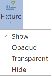
Fixture
enables you to toggle the display of the fixture in the graphic
area of the simulation. |

|
Workpiece
enables you to toggle the display of the workpiece in the graphic
area of the simulation. |
|
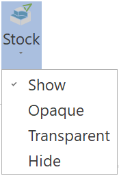
| Stock enables
you to toggle the display of the stock model in the process
of machining.
When the stock is displayed, you can
perform solid verification of the material cutting process
in the SolidVerify mode integrated into the Machine simulation.
The simulation is performed by dynamic subtraction of
the tool solid model (using solid Boolean operations)
from the stock solid model. |

|

|
To perform solid verification
on the stock model, select the Enable
verification check box under Solid
verification section in the Machine
simulation page of the SolidCAM
Settings dialog box. The Stock button is enabled when
the Material removal
option is used in the Simulation tool bar. |
|
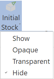 |
Initial Stock
enables you to toggle the display of the stock initial state before
the machining.
|
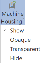 |
Machine Housing enables you
to toggle the display of the machine housing in the graphic area
of the simulation.
|

|
Toolpath
Rendering - This submenu contains commands that enable
you to choose the mode of tool path display.
|
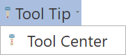
Tool Tip/Tool Center
- these commands enable you to display the tool
path relative to the center or to the tip of the tool. |

|
All
Op - this command
enables you to display the tool path for all of the part
operations all at once.
Current Op
- this command enables
you to display the tool path only for the current operation.
|

|
Thicken
Op - draws thicker
tool path lines for the current operation. |

|
Follow
- this command enables
you to display the already machined tool path. |

|
Trace
- this command enables
you to display the tool path to be machined. |

|
Segment
- this command enables
you to display the segments of the tool path which are
currently being machined. |

|
Tool
Vectors - This command
enables you to display the vectors of the tool tilting
relative to the machined surface. |

|
Toolpath
points - This command
enables you to display the vectors of the tool path by
sequence of points. |

|
Layer
Interval - this
command applies/disregards the tool path filter set at
Layer Interval Settings. The filtered tool path will be
the one contained between the two layer interval planes.
Layer
Interval Settings -
this command configures a visibility filter that contains
the tool path between two planes. |

|
Leads/Links -
these commands enable you to toggle the display of the
tool approach and linking movements. |

|
Current Layer -
this command displays only the layer on which the current
toolpath area is machined. |
|