Visualising and Selecting the Tool Item
SolidCAM ToolKit offers several visualization tools, which can be accessed at the upper right corner of the TOOLKIT dialog box.
Machine Preview
![]() Clicking this button displays
the Machine Preview window.
Clicking this button displays
the Machine Preview window.
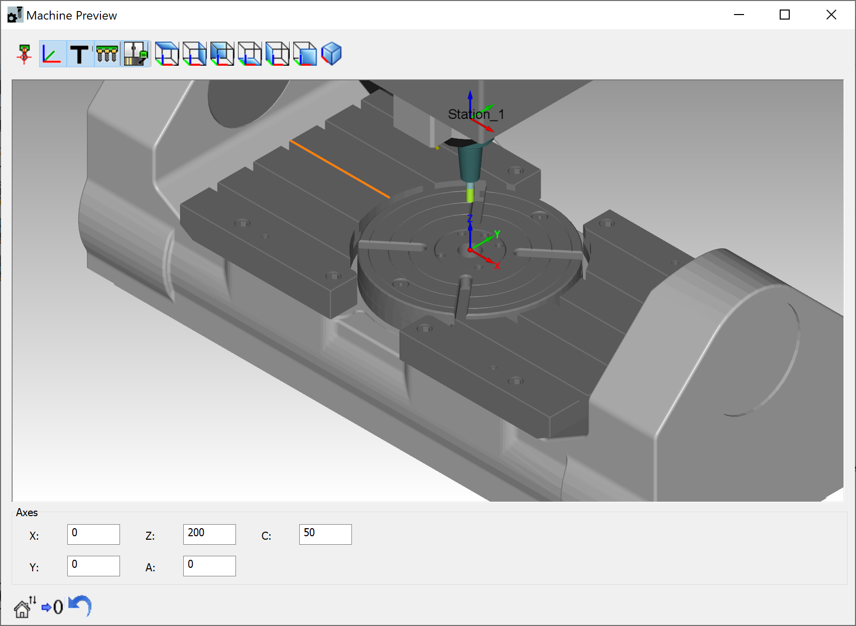
This window enables you to visualize the Tool Item and its schematic position relative to the Machine Coordinate System and in connection with the machine devices without entering the SolidCAM Machine Simulation mode.
Show/Hide Tool Picture
![]() Clicking this button shows/hides
the Tool Viewer window, where you can visualize a 3D model representation
of the Tool Item.
Clicking this button shows/hides
the Tool Viewer window, where you can visualize a 3D model representation
of the Tool Item.
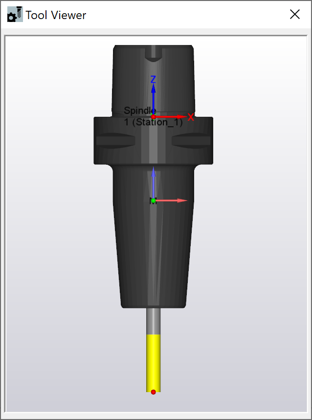
 This window also enables you to view the Tool Item in
different orientations and display styles, take measurements of geometrical
elements (i.e., lines, arcs, splines, edges and points), etc.
This window also enables you to view the Tool Item in
different orientations and display styles, take measurements of geometrical
elements (i.e., lines, arcs, splines, edges and points), etc.
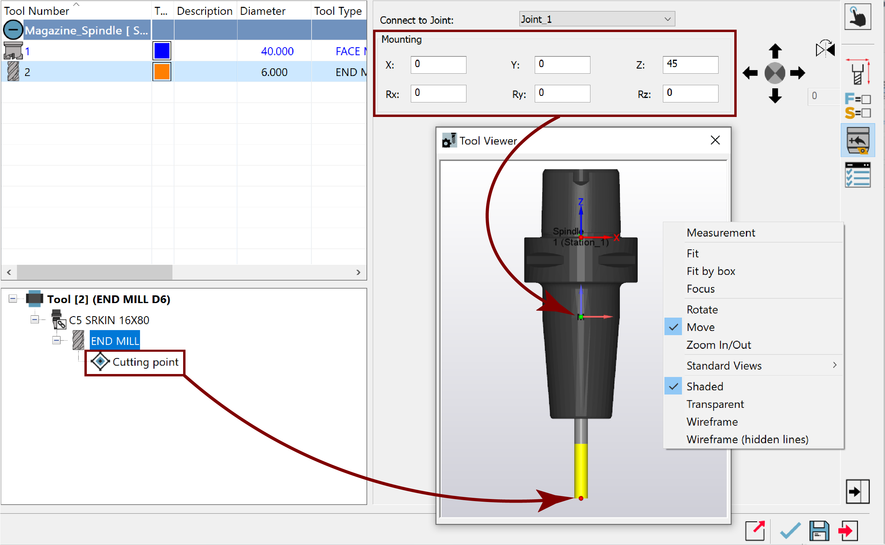
The right-click menu in the Tool Viewer window enables you to manipulate the current view.
The Focus option in the right-click menu enables you to visualize the focussed Tool component selected in the Tool Item Manager.

Show/Hide Tool Near Mouse
![]() Clicking this button toggles
on/off a 3D graphic representation of the Tool Item in the SOLIDWORKS
Graphics Area for performing a visual tool check.
Clicking this button toggles
on/off a 3D graphic representation of the Tool Item in the SOLIDWORKS
Graphics Area for performing a visual tool check.
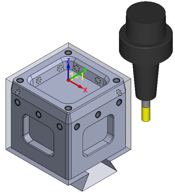
The displayed Tool Item follows the cursor when moving your mouse and it can be dynamically zoomed and rotated together with your 3D CAD model.
The ToolKit visualization tools can be used to facilitate, preview and check your Tool Item definition. Changes you make to the Tool Item are updated instantaneously and can be viewed on the fly.
Related Topics