Left Side of ToolKit dialog box
The left side of the TOOLKIT dialog box contains a number of interface features.
Main menu
![]()
File- The File tab contains the File Managing commands.
- Export
- Export to File
- Save - enables you to Save the current state of the TOOLKIT without exiting the dialog box.
- Save & Exit - enables you to Save all recent changes and Exit the TOOLKIT dialog box.
- Exit - enables you to Exit the TOOLKIT dialog box without saving the recent changes.
View- The View tab enables you to choose the View operation commands.
Swap views - enables you to swap the Part Tool Table view with the Tool Item Manager view.
Unit -The mm and inch options enable you to switch between the Metric and the Inch system of measurement.
Reset dialog size -enables you to restore the default TOOLKIT dialog box size.
Help-
Redirects you to the various SolidCAM Professor video training material.
About ToolKit-Y application... - Displays the dialog box that contains the information about the SolidCAM ToolKit Application version.
Disassociate *.tlv, *.tls, *.tlm - Selecting this option breaks the connection with all the associated Tool Libraries.
ToolKit Filter options
![]()
SolidCAM ToolKit offers an extensive range of simple and advanced filters that can be used to facilitate component searches.
Library Toolbar
This Toolbar contains the buttons to access the available SolidCAM Components and the import options for Third Party Tools and ToolKit Tool Libraries. On Library Toolbar, you can choose the templates that you want to be displayed in the Selection Pane.

(All available SolidCAM Components shown for illustrative purposes)
Selection Pane
This Selection Pane displays the contents of the selected Components/Library from which you can add/import Tool Items into the Part Tool Table.
Component Selection Pane |
Tool Components Library Selection Pane |
Tool Assemblies Library Selection Pane |
Machine Tool Setup Library Selection Pane |
|
|
|
|


Right-click on the Tool type and select the mounting position of the Tool. In the Part Tool Table, the Tool is placed under the mounting position selected.
Narrow/Expand Library Page
Narrow/Expand Library Page ![]() enables
you to toggle between showing and hiding the Selection
Pane. Use
enables
you to toggle between showing and hiding the Selection
Pane. Use ![]() to enlarge or reduce the size of panes in the TOOLKIT dialog box.
to enlarge or reduce the size of panes in the TOOLKIT dialog box.
Part Tool Table
The Part Tool Table is the tool library that contains all tools available for use in a specific CAM-Part. The Part Tool Table is stored within the CAM-Part.

The TOOLKIT dialog box enables you to manage the tools contained in the Part Tool Table. The right-click menu available in the column names of the Table enables you to customize the Tool table.
When the Part Tool Table is empty or if no suitable Tool Items are available for selection, one must be added and defined accordingly.
|
If Operation default templates are selected in the SolidCAM Settings or the Part Settings, a Tool Item suitable for the current operation may be loaded automatically. In such cases, the Tool Item can be edited as necessary. |
Tool Item Manager
The Tool Item Manager displays the selected Tool Item in a hierarchical tree structure as an assembly of individual tool components. The Tool Item Manager enables you to view/edit complete information about the Tool Item.
The Tool Item Manager (in Tool Assemblies, Machine Tool Setup and Part Tool Libraries) enables you to easily create tool assemblies, aka Tool Items. It is built upon the Cutter with additional components such as Shanks, Adaptors & Holders.
Tool Item tree selection determines data displayed and parameters/options availability.
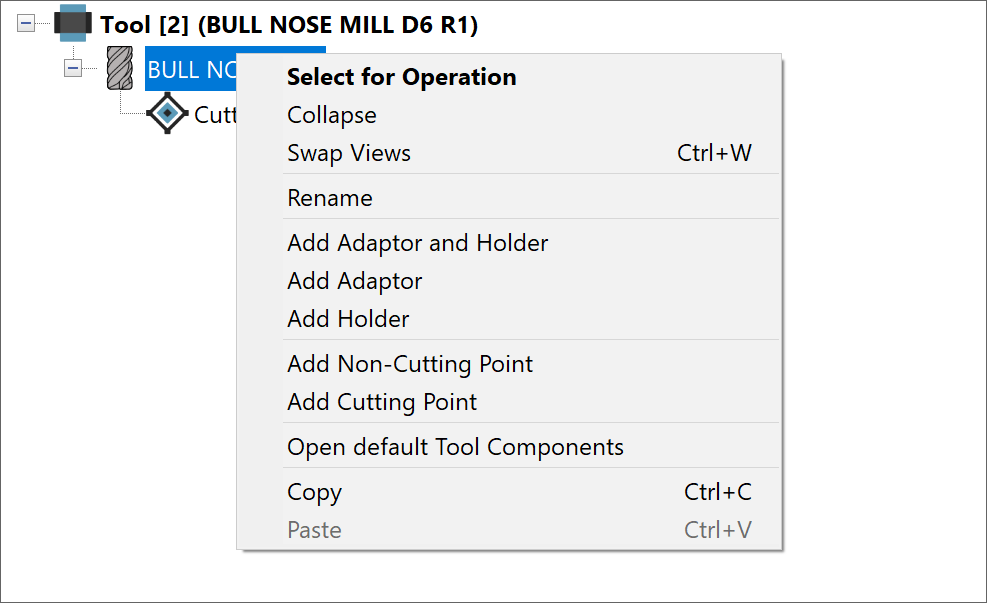
Select for operation - This option is available when a Tool has to be added in a New Operation or Tool has to be changed in an already defined Operation.
Expand / Collapse - Expands or Collapses the Tool Items.
Swap Views - enables you to swap the Tool Item Manager view with the Part Tool Table view.
Permanent Tool
- If a particular tool is always used in the same magazine position in
the Machine, this tool can be marked as Permanent Tool. You can also mark
a Tool as a Permanent tool by selecting the Permanent Tool check box in
the Quick Data Access
section. The Permanent Tool number with suffix P
is displayed in bold in the Part
Tool Table eg. ![]() to mark Tool no.5 as a Permanent Tool.
If you use the Renumber Tools function,
a tool marked as Permanent Tool is not renumbered.
to mark Tool no.5 as a Permanent Tool.
If you use the Renumber Tools function,
a tool marked as Permanent Tool is not renumbered.
Rename - enables you to Rename the Tool Items.
Add Adaptor and Holder - enables you to add the Adaptors and Holders manually.
Add Adaptor - enables you to add only the Adaptor manually.
Add Holder - enables you to add the only the Holder manually.
Add Non-Cutting point - enables you to add a Non-Cutting point. Non-Cutting point is measured on any Tool item, used for MCO operations (Stopper tool offset, Tail stock tip etc.)
Add Cutting point - enables you to add a Cutting point. Cutting Point is a measured point on the cutter, used in Machine offset table.
Open default Tool Components - enables you to open the predefined Tool Components Library.
Copy - enables you to copy the selected Tool Item.
Paste - enables you to paste the selected Tool Item.
Related Topics