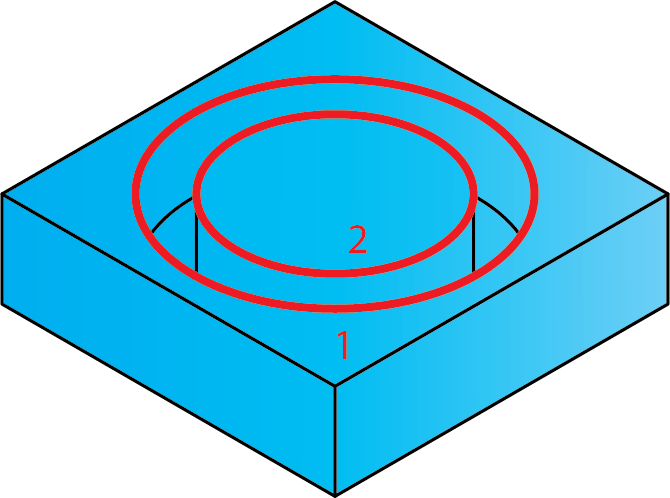
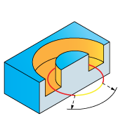
O-Ring
The geometry defined for this ToolBox Cycles strategy consists of a pair of closed chains with one chain surrounding the other; accordingly, the geometry should contain at least two closed chains. During the geometry definition, SolidCAM checks its chains for suitability. The geometry containing one closed chain is considered as unsuitable. The geometry containing more than one closed chain is considered as suitable. The mixed geometry containing a number of open and closed chains (more than one) is considered as suitable, but all the open chains are ignored during the tool path calculation.
Geometry definition
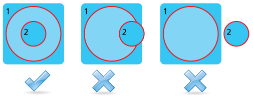
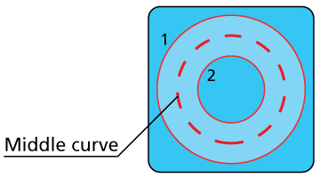
A subset of closed chain pairs is used for this sub-operation. In each such pair, the first chain is considered to be external, the second one is considered to be internal.
The external (first) chain should completely surround the internal (second) chain. Intersections between internal and external chains can cause errors during the tool path calculation. The case when the external geometry does not surround the internal geometry can also cause errors during the tool path calculation.
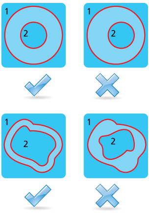
The shape of the chains included into the pair can be various, but the equal distance between chains should be maintained along the whole chain. In other words, the chains should have similar shape and should be located at a specific offset one from the other.
During the geometry parsing, SolidCAM takes first closed chain and considers it as the external contour of the first pair, the second closed chain is considered as the internal contour of the first pair. The third chain is considered as the external contour of the second pair, and so on. If the geometry contains an odd number of closed chains, the last chain is rejected.
The direction of the chains is not important for the O-Ring sub-operation.
Technological parameters
Rough
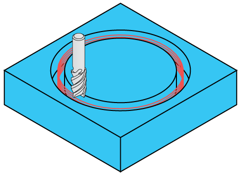
The O-Ring machining is performed in rough and finish cutting passes. The rough cutting pass is a spiral cut performed at the middle line between two geometry chains. There are three ways to define the roughing cuts: by step down, by angles, or by number of cuts.
The spiral step is defined by the Rough Step down parameter. The spiral rough cut is performed up to the Floor offset distance from the Depth level (defined at the Levels page).
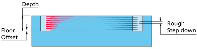
The finish machining of the O-Ring is performed in a number of cutting passes distributed along the tool axis. The distance between two successive cutting levels is defined by the Step down parameter. The Equal step down option enables you to define a number of evenly distributed cutting levels. SolidCAM automatically calculates the actual step down to keep an equal distance between all passes, while taking into account the specified Max. Step down value so that it is not exceeded.
Center cutting
Center cutting allows you to enter an angle until a specific depth, clean that depth and then go down in an angle to the next step down depth. When the Center cutting check box is enabled, the Step down is disabled.
This field enables you to define the angle used to approach the starting point. The approach movement starts from the defined safety distance and gets to the starting point along the defined chain.
This field enables you to define the angle used to retract from the end of the chain. The retract movement starts from the end of the chain and gets to the defined safety distance along the defined chain.
This field enables you to define how many rough cuts are performed.
Extension/Overlap
This field enables you to define the overlap of adjacent tool paths.
Offsets
This section enables you to define the Wall and Floor offsets for the O-Ring sub-operation. The Wall offset is applied to the walls of the O-Ring: internal as well as external; the specified offset is left unmachined during the current sub-operation. The Floor offset is applied to the floor of the O-Ring; the specified offset is left unmachined during the current sub-operation. When the Floor offset value is specified, the machining is performed by the Z-levels defined with the Step down parameter. The machining is performed up to the Floor offset above the Depth level.
Compensation
If the Compensation check box is selected, the tool radius compensation options G4x of the CNC-controller are used in the GCode.
Finish
The Wall finish option enables you to perform a final finishing pass cleaning the walls. You can specify the Step down value in a separate field.
Tool path calculation
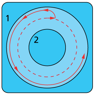
During the tool path calculation, SolidCAM determines the middle curve between two chains.
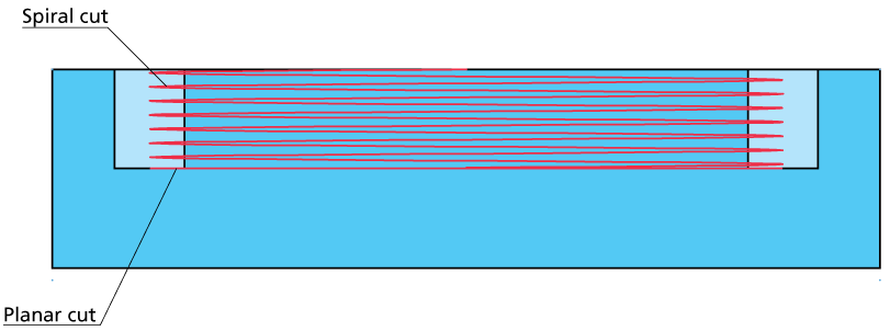
At the next stage, the spiral rough cutting pass is generated along the middle curve. The spiral starts at the Safety distance level. The machining is performed in the CCW direction. The spiral machining is performed until the Floor offset level above the Depth level is reached.
When the Floor offset level is reached, SolidCAM performs at this level the planar tool movement along the middle curve. This movement is performed in order to clean the material at the floor and make the floor planar.
At this point, the rough cut is completed and the tool moves to the first Step down level of the finishing and then starts the finish machining.
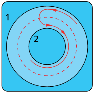
At the beginning of the finish cut, the tool descends to the first cutting level defined by the Finish Step down parameter. At this point, the tool performs the horizontal linear movement in the positive X-axis direction at the distance equal to half of the distance between the chains minus the double Wall offset distance. From this point the tool performs a radial lead in motion to the external contour. The radius of the lead in motion is equal to half of the distance between the chains minus the double Wall offset distance. After the lead in movement, the machining of the external wall (taking into account the Wall offset) is performed. The climb milling is performed along the tool path.
When the external wall is completely machined at the successive Z-level, the tool performs a radial lead out movement with the same radius. The lead out movement is blended into the lead in movement to the internal wall finishing tool path.
The internal wall finishing tool path is also performed maintaining the climb machining. When the finish tool path is completed, the tool exits from the material with the lead out arc of the same radius and performs the linear movement in the to the arc center.
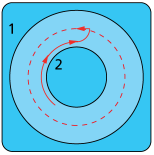
At this point, the tool descends to the next cutting level.