Preparing a CNC-Machine model
Machine simulation requires a model of the CNC-Machine in the STL format. Such model can be either supplied by a CNC-Machine vendor or prepared by yourself in a CAD system. When the CAD model of the CNC-Machine is prepared, it can be exported into a number of STL files, each one representing a different component of the CNC-Machine.
The image below shows a schematic model of a Table-Table CNC-Machine built in SOLIDWORKS.
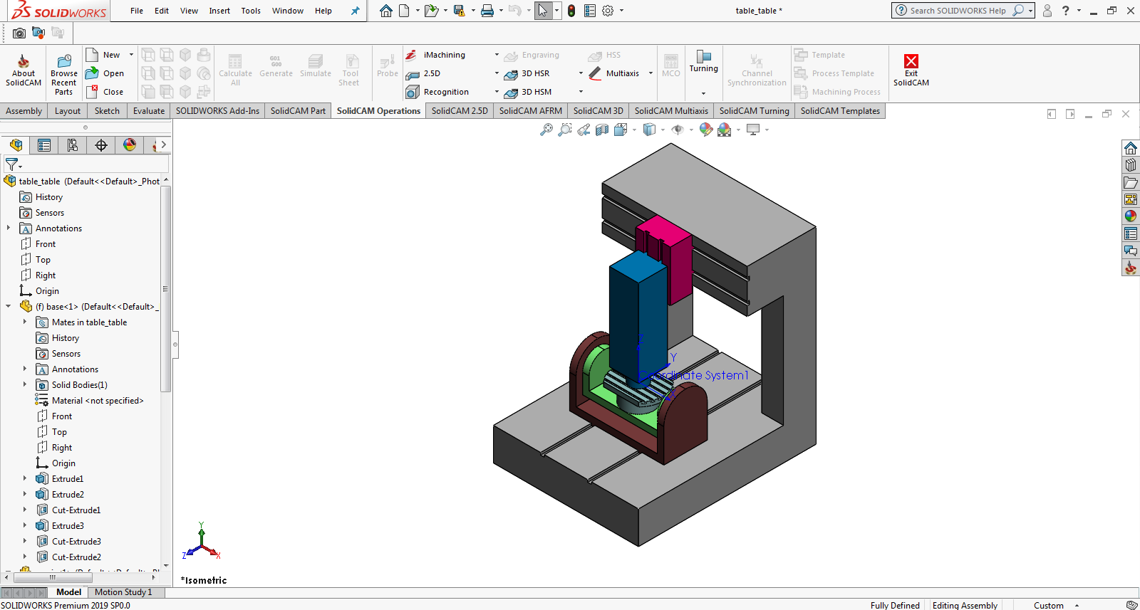
Each STL file has to be created using an output coordinate system located at the CNC-Machine origin. If the coordinate system of your CNC-Machine assembly is different, you have to define an additional coordinate system with the proper location and axes orientation.
For the Table-Table machine shown above, you have to define a new coordinate system located in the intersection of the top face of the table and the rotational axis (CNC-Machine origin).
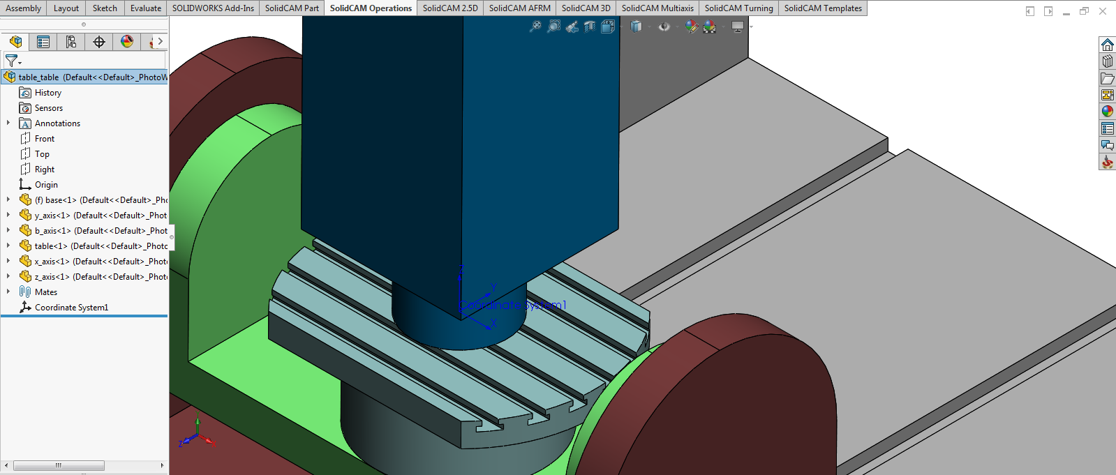
When the coordinate system is defined, move all the components into their initial state (the components performing rotational axes movements have to be placed into their initial state at C=0, B=0; the components performing translational axes movements have to be placed at X=0, Y=0, Z=0).
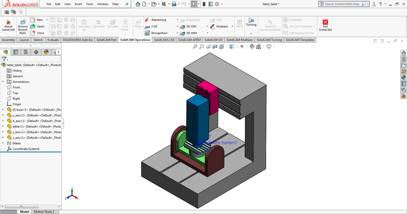
After the coordinate system is defined and all the CNC-Machine components are placed into their initial state, the CNC-Machine model has to be exported into the STL format.
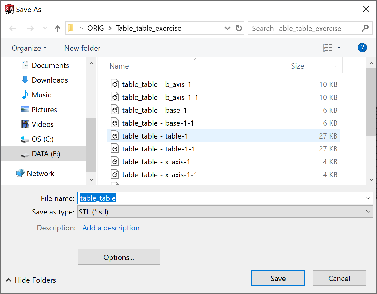
Click File, Save As. The Save As dialog box is displayed.
Choose the STL type for export of the model. Click the Options button to define the additional parameters of export.
The Export Options dialog box is displayed.
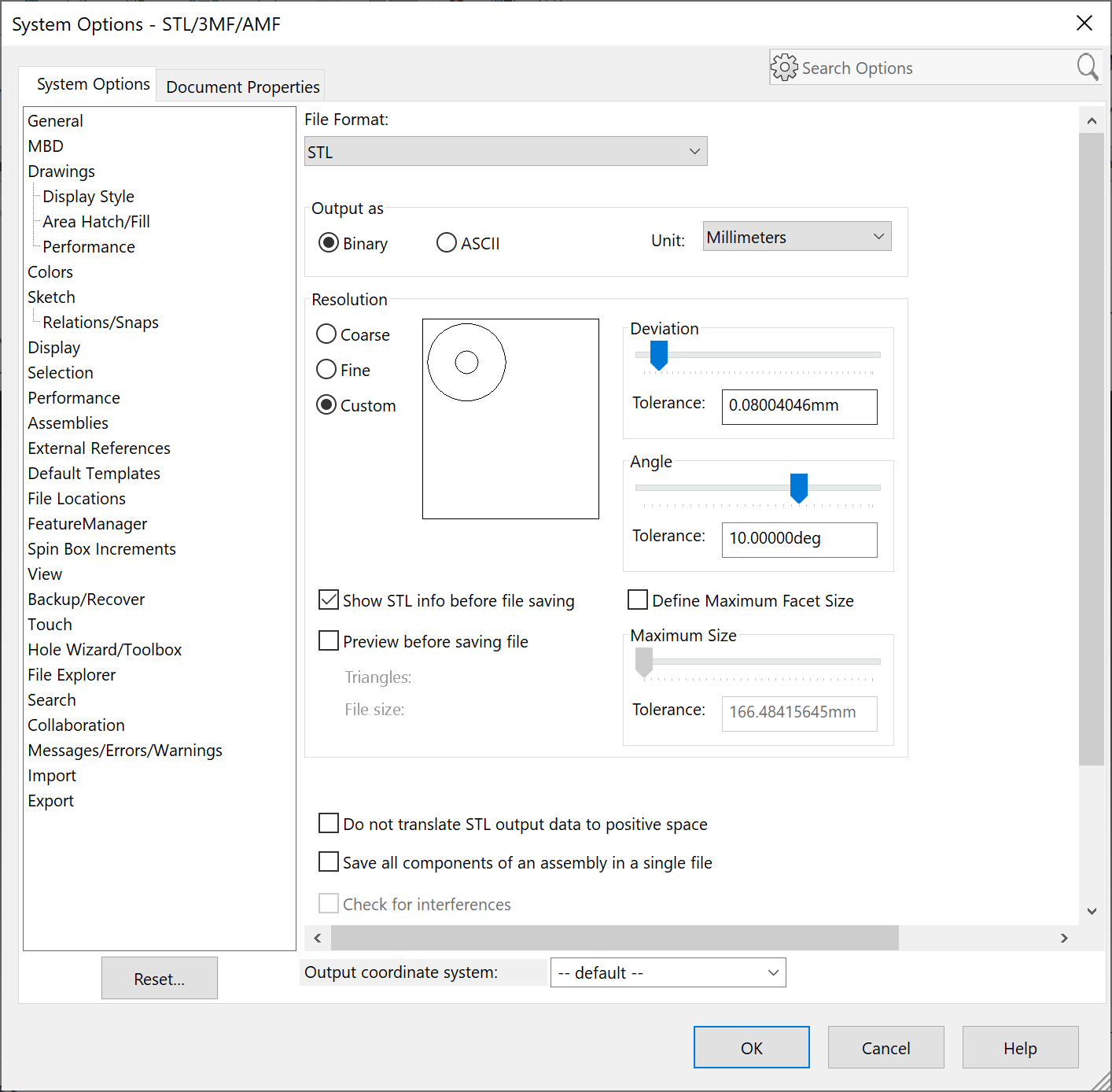
This dialog box enables you to define a number of parameters affecting the STL export. See SolidWorks Help for detailed explanation.
Adjust the STL Resolution parameters according to your needs.
In the Output coordinate system list, choose the defined Coordinate system for the STL export.
Select the Do not translate STL output data to positive space check box. This option ensures that exported parts maintain their original position in global space, relative to the origin.
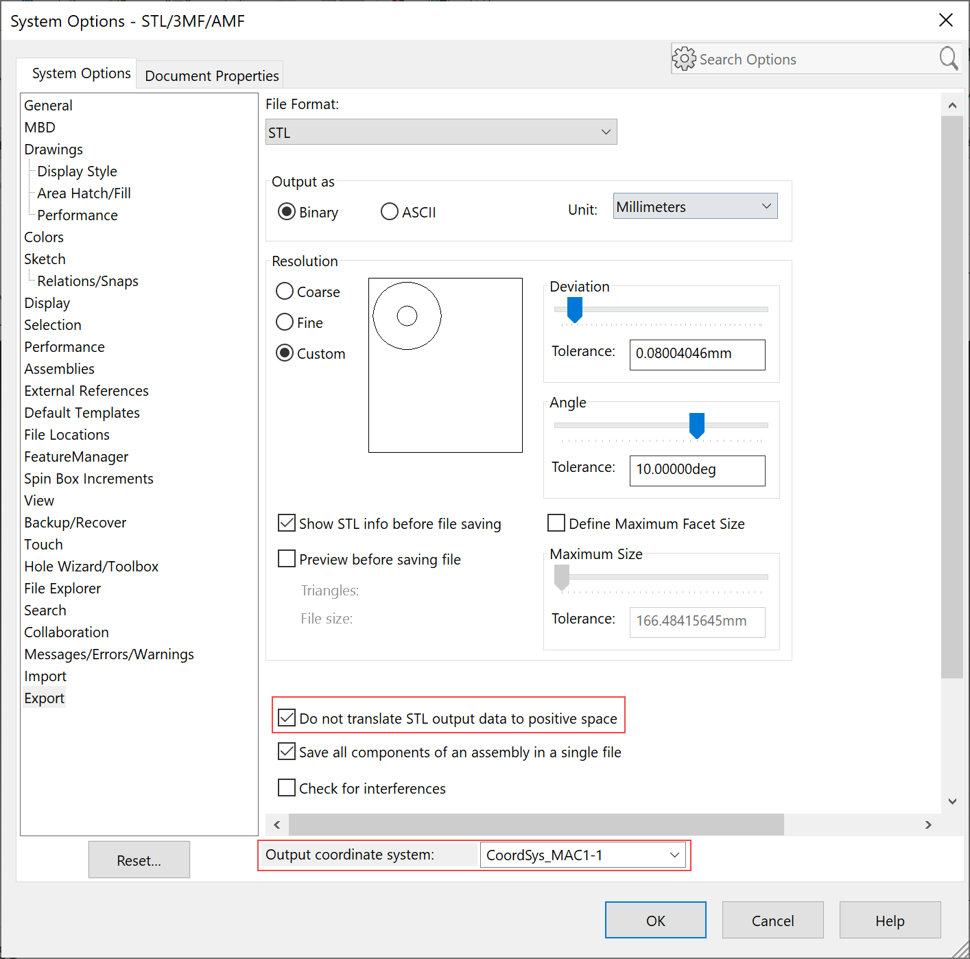
Confirm the Export Options dialog box with the OK button.
In the Save As dialog box, choose the location for the STL files and enter the name of the STL file for the CNC-Machine assembly. Confirm the export with the Save button. Several separate STL files for all the CNC-Machine assembly components are generated. All of these files will be used at the further stages of the CNC-Machine definition.
|
A CNC-Machine model consists of a number of components. It is recommended to try to define the CNC-Machine with the minimum number of STL files. To reduce the number of STL files, you can put several components together in one sub-assembly that is exported into a single STL file; the criterion for putting several components into one STL file is the common movement of these components. When assembly components always move together, they can be combined into a sub-assembly. For example, the model of the spindle unit of a Table-Table CNC-Machine consists of a number of components that have a common movement; according to the criterion above, all these spindle unit components can be combined into a sub-assembly. Such sub-assemblies can be exported separately into STL files using the Save all components of an assembly in a single file option in the Export Options dialog box. This option creates a single STL file with all the components of a sub-assembly. Before the export of a sub-assembly, the new coordinate system has to be defined in the sub-assembly in the location of the CNC-Machine origin. |
Related Topics