Quick SolidVerify simulation mode
This simulation mode is used for 3D visualization of operations.
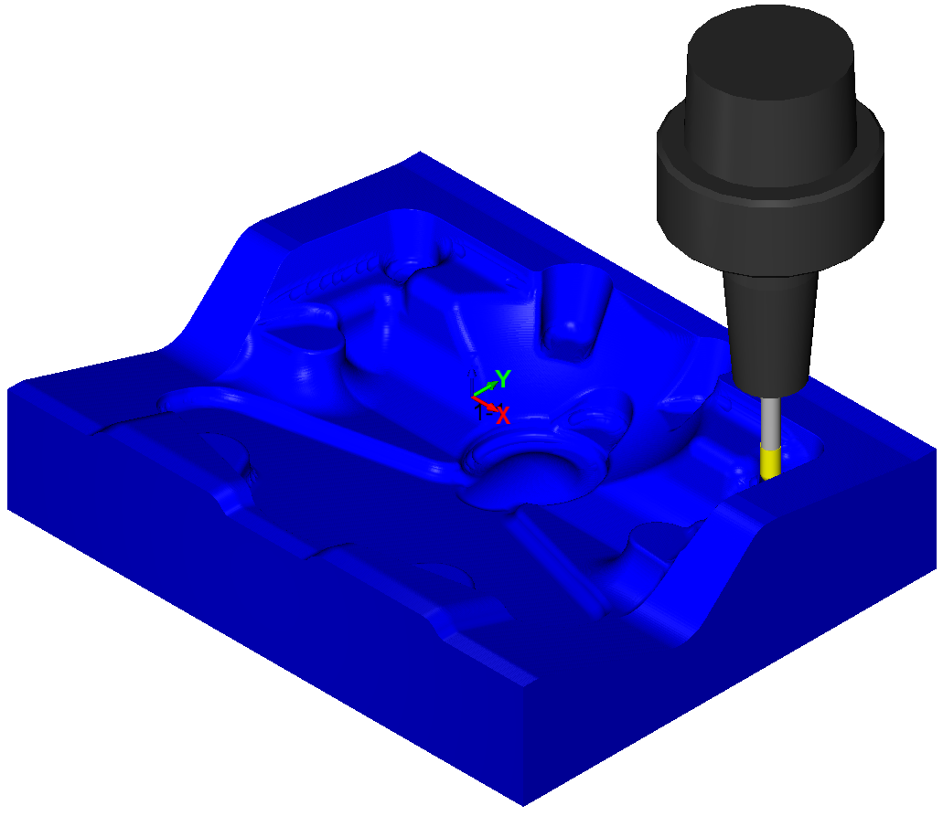
Quick SolidVerify creates a very accurate model of the machined stock by storing the analytical definitions of all surfaces that are created during machining. SolidVerify for 3D has been built to enable fast processing of parts with complex 3D geometry (e.g die/mold) and long tool paths.
The difference between Quick SolidVerify and the regular SolidVerify is as follows: SolidVerify works with facet representation of the model and tool; the facet model of the stock model is created, and the facet model of the tool is subtracted from it for each tool movement. On the other hand, Quick SolidVerify works with analytical geometry in order to represent the updated stock. All the calculations are performed for analytical geometry, the resulting surface mesh is generated and rendered in order to visualize the cutting process. Since Quick SolidVerify uses more precise analytical data, the visualization result is more accurate, especially in close zoom.
Increasing simulation speed and rendering performance
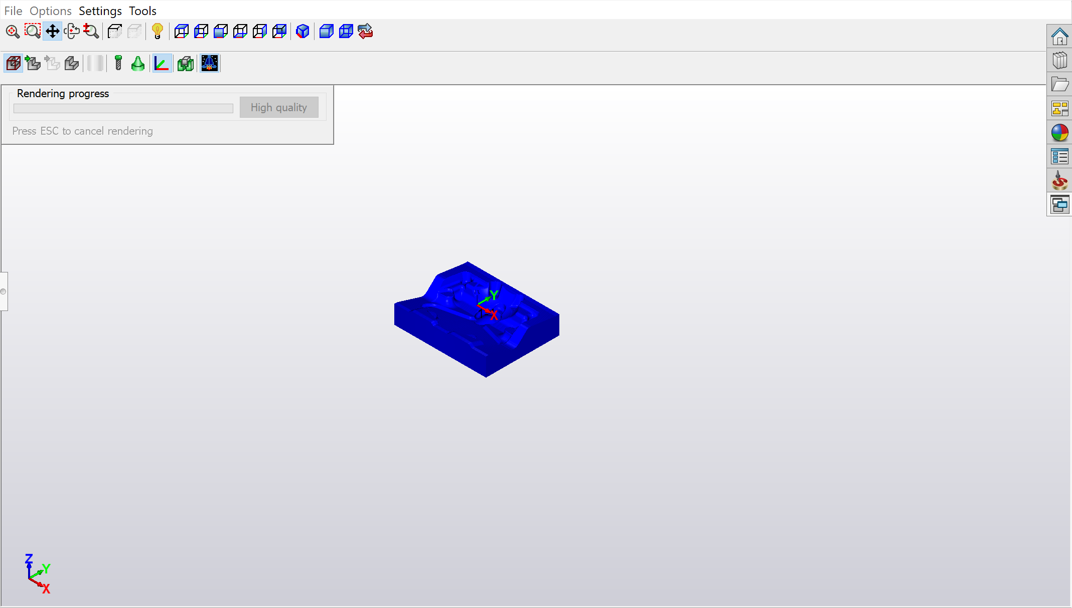
The simulation speed and rendering performance depend on the size of the model in the simulation view. To increase the performance, it is recommended to zoom out the model before the simulation and hide the tool and holder. When the simulation reaches a specific area that you want to check in depth, you can zoom in to this area and perform a high quality rendering of the simulation model.
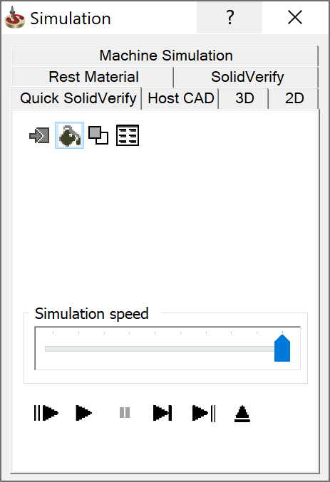
Simulation control panel
Rendering of the simulation model
Rendering of the simulation model is performed in two modes: