Simple Boss
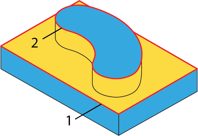
This ToolBox Cycles strategy enables you to perform machining of a boss located on a model face. SolidCAM enables you to define the closed geometry chain for the boss and closed chain for the initial model face from which the boss starts. The machining is performed in a number of equidistant cutting passes parallel to the boss geometry. The passes are cut with the outer contour of the initial face.
![]()
Geometry definition
The strategy provided by this sub-operation can be performed only on pair of closed chains with one chain surrounding the other. Therefore, the geometry should contain at least two closed chains. The geometry containing only open chains is considered as not suitable. The geometry containing one closed chain is considered as not suitable. The geometry containing more than one closed chain is considered as suitable. The mixed geometry containing a number of opened and closed chains (more than one) is considered as suitable, but all the open chains are ignored during the tool path calculation.
A subset of closed chains pairs is used for this sub-operation. In each pair, the first chain is considered external, the second one is considered internal.
Intersections between the geometry chains are not acceptable.
The direction of the geometry chains is not considered during the tool path calculation.
Technological parameters
Rough
SolidCAM enables you to perform the boss machining in a number of rough cutting passes distributed along the tool axis.
Step down
The distance between two successive cutting levels is defined by the Step down parameter. The Equal step down option enables you to define a number of evenly distributed cutting levels. SolidCAM automatically calculates the actual step down to keep an equal distance between all passes, while taking into account the specified Max. Step down value so that it is not exceeded.
Step over
The Step over parameter defines the distance between two successive cutting passes equidistant to the boss geometry.
Direction
This section enables you to define the tool path direction. The tool path consists of a number of closed cutting passes performed around the boss and a number of trimmed cutting passes. During the tool path linking, SolidCAM sorts the tool path by areas. The machining of the closed cutting passes around the boss shape is performed in the climb direction. The machining of the trimmed open passes is performed according to the One way/Zigzag options.
When the One way option is chosen, SolidCAM performs the machining of the area in a number of unidirectional cutting passes, maintaining the climb direction for all the passes. A one way path has many retractions; after the machining pass the tool has to perform a movement to the start point of the next pass.
When the Zigzag option is chosen, both Climb milling and Conventional milling methods are used in the bidirectional tool path.
Offsets
This section enables you to define Wall and Floor offsets for this sub-operation. The Wall offset is applied to the walls of the boss; the specified offset is left unmachined during the current sub-operation. The Floor offset is applied to the floor of initial face from which the boss starts; the specified offset is left unmachined during the current sub-operation. When the Floor offset value is specified, SolidCAM performs the machining by the Z-levels defined with the Step down parameter. The machining is performed until the Floor offset level.
Finish
The Wall finish option enables you to perform a final finishing pass cleaning the walls. You can specify the Step down value in a separate field.