SolidCAM Simulator (Beta)
In the CAM Manager, right-click the Operations header and choose SolidCAM Simulator (Beta). The SolidCAM Simulator (Beta) window is displayed.
To simulate an existing operation,
right-click an existing operation
and choose SolidCAM Simulator (Beta) or in the operations window, click Ctrl+![]() to open SolidCAM Simulator (Beta) window instead
of the standard Simulation control
panel.
to open SolidCAM Simulator (Beta) window instead
of the standard Simulation control
panel.
|
Pop-up
messages will break the control short cut, Ctrl+ |
Flyout Window display
The Flyout Window is the default mode and displays the resizable floating
SolidCAM
Simulator (Beta) window. Simulation can be kept open and running while
actively working in SolidCAM/SOLIDWORKS
. To change the default, right-click ![]() in the SolidCAM Simulator (Beta) window
and disable the Flyout Window option.
in the SolidCAM Simulator (Beta) window
and disable the Flyout Window option.
Integrated display
Right-click ![]() in the SolidCAM Simulator (Beta) window
and disable the Flyout Window option to enable the Integrated display
option. The SolidCAM Simulator (Beta) is
displayed in the SOLIDWORKS graphics area. The Simulation conceals
the CAD model. All the features of Simulator can be used while actively
working in SolidCAM/SOLIDWORKS
.
in the SolidCAM Simulator (Beta) window
and disable the Flyout Window option to enable the Integrated display
option. The SolidCAM Simulator (Beta) is
displayed in the SOLIDWORKS graphics area. The Simulation conceals
the CAD model. All the features of Simulator can be used while actively
working in SolidCAM/SOLIDWORKS
.
|
SolidCAM recalls the last Simulation state while toggling between Integrated and Flyout Window display when a new CAM-Part is opened. |
Minimized mode
Minimized mode is an alternative
display option when using the Integrated simulator display. Minimized
mode displays a small scalable version of the simulation in the SOLIDWORKS
display area separate from the CAD model. Click ![]() on the Simulator model to move the Mini-mode to any preferred region in
the SOLIDWORKS display area.
on the Simulator model to move the Mini-mode to any preferred region in
the SOLIDWORKS display area.
GUI features

Rest material control panel
This section is displayed when Compare Target and machined stock...is selected in the Simulator menu. The Rest material control panel enables you to dynamically compare the Target to the machined stock during simulation. You can view the rest material according to the specified sets of colors and tolerances. The default tolerances f(x) is based on CAM-Part Tool facet tolerance.
The Rest material control panel enables you to:
- Visualize the rest material by turning On/Off
 .
.
- Change the visualization colors by scrolling the vertical color slider.
- Modify tolerances by turning On/Off f(x).
Simulation controls
The Simulation controls are used to manage the simulation.

|
Record
removed material
You can enable/disable recording by clicking
this icon. Records each tool path which enables you to
play forward and backwards solid verification using the scroll
bar on the Operations timeline. When recording starts a red line
appears over the operation timeline slider indicating that the
tool path is being recorded.
|
||
|
Skip Operation Back Click to skip single operation backwards. Press and hold to skip multiple operations backwards. | ||
|
Step back Click to move single step backwards. Press and hold for multiple steps backwards. | ||
|
Play in Reverse Plays the simulation in reverse mode. | ||
|
Pause Pauses the simulation when performed in continuous play mode. | ||
|
Play Plays the simulation in continuous mode. | ||
|
Step Forward Click to move single step forward. Press and hold for multiple steps forward. | ||
|
Skip Operation Forward Click to skip single operation forward. Press and hold to skip multiple operations forward. | ||
|
Playback Speed Slider
|
||
|
Operations timeline slider
|
Simulation Playback Modes
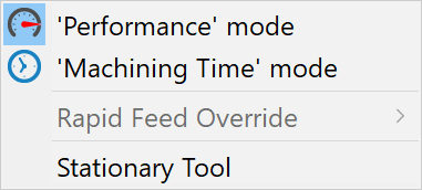
You have the option to use either Performance
mode or Machining Time mode when running Simulation playback. Click ![]() the
Playback options menu, where the Simulation Playback modes can be chosen.
the
Playback options menu, where the Simulation Playback modes can be chosen.
|
The icon for the currently running Playback Mode is displayed in the Status bar. |
Performance mode
This mode is set as default. Performance mode plays the simulation at incremental speeds based on the playback speed slider. The slider blue segments represent the tool path engine calculations using a single core. In the blue segment, generally the on screen tool path re-drawn is smooth during simulation playback. The slider red segments represent calculations using multi-core support which provides increased performance with up to 30% or 5 times faster speeds. This option is a great choice for simulating 3D and 5 Axis tool paths where playback can be long due to lengthy calculation times.
|
Increasing the slider speed reduces the playback smoothness. |
Machining Time mode
Machining time mode plays the simulation in accordance with the actual time spent running on the machine. Center of the slider yellow segments simulates real time machining equivalent to 1 times the speed. Using the slider you can increase or decrease the speed relative to the actual machining time. In addition to the pre-defined 0.1 times to 64 times speeds, it is possible to enter a preferred speed using the playback speed edit box.
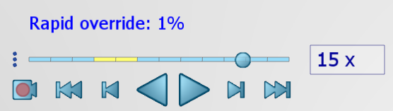
The Machining Time mode also enables you to independently adjust the speed at which rapid moves are simulated. You can manually slow down these movements on the machine with an override dial, likewise you can now simulate the same actions using the Rapid Feed Override option. Using this option, it is possible to decrease the rapid move simulation by 50% , 25% or 1% of the actual speed giving you greater control over the visualization. The selected override will appear above the playback speed slider.
Status Bar
![]()
The SolidCAM simulator status bar provides us with plenty of useful information:
- Current state of the stock which changes while running and resetting the simulation or when reloading the stock model display.
- Currently selected Playback Mode as well as the operation being simulated.
- Currently simulated operation tool path step and the X, Y and Z position of the tool.
- Time, Feed and Spin data corresponding to the current location of the 'Operations bar' Slider and Thumb when playback is running.
|
When hovering the mouse pointer over the simulated operation tool path in the graphics area, the status bar will display data corresponding to the specific tool path points. |
Tool path features
SolidCAM Simulator (Beta) imparts the following Tool path features:
|
|
|
|
|
|
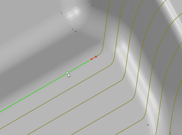
Timeline jump-to feature
Two methods are available for advancing forward or backward to any point in the tool path.
Method 1: Use the slider on the Operations timeline or your mouse wheel to scroll the tool path to add or remove the appearance of tool path from the graphics window. This feature is useful for simulating long tool paths. You need not wait for the entire tool path to play.
Method 2: Jump to a spot in the tool path and snap the tool to its position by clicking a segment or Double-click on the tool path, the simulation will jump to that position. When combined with Solid Verification it is useful for visualizing engagement of the tool with the stock material in area of focus.
Dynamic highlighting
You can dynamically highlight faces, edges and vertices on the Machined Stock at any stage of the simulation. Highlight one item by selecting it or multiple items at a time by holding the Ctrl key to multi-select them.

You can highlight one item eg. an edge by selection.

Hover highlighting on this item indicates when your pointer is poised to select an item.

Dynamic measuring
You can dynamically measure one item or a combination of multiple items (up to six) at any stage of the simulation. Simply highlight the item(s) you want to measure. You can take the Machined Stock measurements in simulation, such as between jobs, and verify on the machine for accuracy.
Measurements data appears at the bottom right corner of the graphics area:
![]()
Data options and indicators are shown when you hover your mouse:

You can easily and accurately measure a combination of faces, edges and vertices.
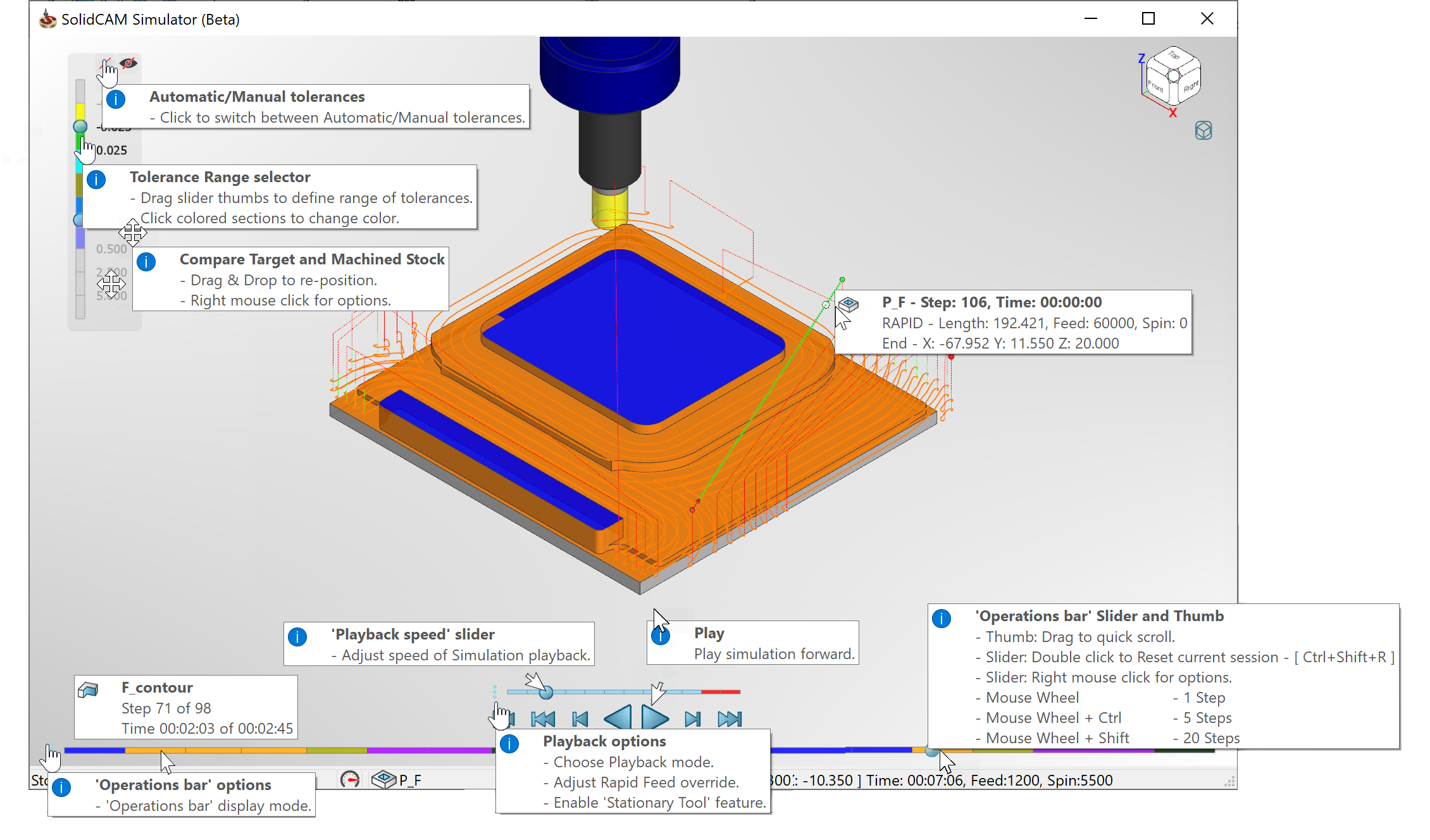
Dynamic tool tips
As you hover your mouse pointer over SolidCAM simulator options and controls you will see the appearing tool tips. Each tool tip provides you with helpful descriptions.
Tool tips are displayed for the available playback options and the operation bar options. Additionally, the operations bar displays details such as operation types, tool path steps and corresponding machining times. The 'Operations bar' Slider and Thumb shows valuable information on the different ways to advance through the simulation and for resetting the current session.
Dynamic tool tips are available for Compare
Target and Machined Stock controls. You can drag the Rest Material Control
Panel and reposition it in the graphics area. Enable/Disable ![]() to toggle On/Off the Target and Machined Stock Comparison. Enable/Disable
to toggle On/Off the Target and Machined Stock Comparison. Enable/Disable
![]() to toggle between Automatic and Manual tolerances. You can use Automatic
tolerances whose values are generated according to the tool facet tolerance
or use Manual tolerances whose values can be entered manually in the edit
boxes. You can also modify range and color indication of tolerances by
using the tolerance range selector.
to toggle between Automatic and Manual tolerances. You can use Automatic
tolerances whose values are generated according to the tool facet tolerance
or use Manual tolerances whose values can be entered manually in the edit
boxes. You can also modify range and color indication of tolerances by
using the tolerance range selector.
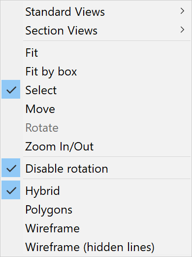
Simulator Graphics Area right-click menu options
You can rotate the Model using the arrows on the keyboard.
Right/Left arrow - Vertical axis
Up/Down arrow- Horizontal axis rotation.
Alt + Left or Right arrows - Rotates the model normal to the current viewing plane.
Shift + Left or Right arrows - 90° rotation around vertical/horizontal axis.
The right-click menu in the Simulator graphic area enables you to manipulate the current view.
 |
|