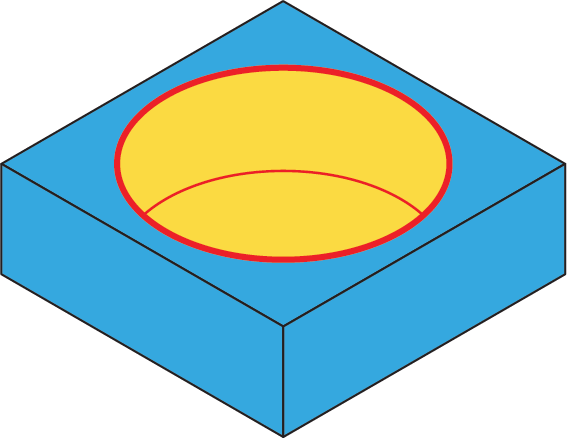
Spiral pocket
This ToolBox Cycles strategy enables you to perform machining of the closed pocket areas using spiral techniques. With this strategy, the tool penetrates into the material in the automatically calculated point inside the pocket with a helix (with the automatically calculated radius and angle). Then the tool performs the spiral cutting pass morphing from the penetration point to the closed area walls.

Geometry definition
The strategy provided by this sub-operation can be performed only on round closed chains. Therefore, the geometry should contain at least one closed chain. The geometry containing only closed chains is considered as suitable. The geometry containing only open chains is considered as not suitable. The mixed geometry containing a number of opened and closed chains is considered as suitable. With such geometry, all the open chains are ignored during the tool path calculation.
SolidCAM does not check the intersection between chains and surrounding of one chain by another chain.
Geometry definition rules
The Spiral pocket sub-operation is intended to perform machining of round closed areas. If the geometry is not circular, the error message is displayed.
Technological parameters
Rough
SolidCAM enables you to perform the spiral pocket machining in a number of rough cutting passes distributed along the Z-axis.
Step down
The distance between two successive cutting levels is defined by the Step down parameter. The Equal step down option enables you to define a number of evenly distributed cutting levels. SolidCAM automatically calculates the actual step down to keep an equal distance between all passes, while taking into account the specified Max. Step down value so that it is not exceeded.
Spiral cuts
This section enables you to define the parameters of the spiral cuts. Spiral tool path generated by this sub-operation consists of a number of recurrent spiral cutting passes. Two successive cutting passes can be defined either by distance or by angle. The Step over parameter enables you to define the distance between two successive cutting passes, setting it in the range between the Min step over and Max step over. The Angle parameter enables you to define the angle between two successive cutting passes, setting it in the range between the Min cutting angle and Max cutting angle.
Helical Entry
When this check box is not selected the tool plunges vertically into the material.
When this check box is selected the tool approaches the surface with a helical entry. You can define the Helical angle with which the tool approaches the surface. When the Helical angle is set to 0 or 90 the tool plunges vertically into the material, and no helical movement is performed.
Offsets
This section enables you to define Wall and Floor offsets for this sub-operation. The Wall offset is applied to the walls of the pocket; the specified offset is left unmachined during the current sub-operation. The Floor offset is applied to the floor of the pocket; the specified offset is left unmachined during the current sub-operation. When the Floor offset value is specified, SolidCAM performs the machining by the Z-levels defined with the Step down parameter. The machining is performed until the Floor offset level.
Finish
The Wall finish option enables you to perform a final finishing pass cleaning the walls. You can specify the Step down value in a separate field.
The Floor finish option enables you to perform final finishing cuts cleaning the floor.
Compensation
If the Compensation check box is selected, the tool radius compensation options G4x of the CNC-controller are used in the GCode.