The structure of the CAM-Part
External mode
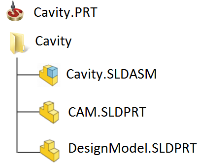
The Cavity CAM-Part defined in the External mode includes the following :
|
|
SolidCAM copies the original SOLIDWORKS model to the Cavity subdirectory and creates a SOLIDWORKS assembly that has the same name as the CAM-Part (Cavity.sldasm). There are two components in this assembly:
DesignModel.sldprt – a copy of the SOLIDWORKS model file.
CAM.sldprt – a file that contains SolidCAM Coordinate Systems and geometry data.
The Cavity subdirectory also contains the files that contain the stock and target geometry.
SolidCAM CAM-Part uses the assembly environment of SOLIDWORKS. This enables you to create auxiliary geometries (e.g. sketches) without making changes in the original design model. You can also insert some additional components into the assembly file such as stock model, CNC-Machine table, clamping and other tooling elements.
Internal mode
When the CAM-Part is defined in the Internal mode, all geometries are stored within the CAD file. A new folder with the CAM-Part name is created in the FeatureManager Design Tree, and all CAM files are located under the folder.
Related Topics