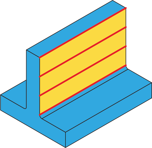
Thin wall machining
This ToolBox Cycles strategy enables you enables you to machine thin walls while removing gradually the excess material from either side of the wall. The method can be chosen from two options: Alternating steps or Supporting steps.
Geometry definition
The list of available geometries contains only suitable geometries.
Suitable geometries
|
 |
Technological parameters
Rough
SolidCAM enables you to perform thin wall machining in a number of rough cutting passes distributed along the tool axis.
Strategy
This section enables you to choose one of two strategies: Alternating steps or Supporting steps.
In the Supporting steps strategy, the tool first makes a cutting pass at the level equal to the half of Step down on one side of the wall, then it makes a cutting pass at the level of the full Step down on the other side of the wall. This way the material is removed gradually from either side of the wall, while the difference between the cutting levels provides necessary support for the thin wall. This strategy is recommended for the walls where the ratio of the wall thickness to height is smaller than 1:30.
In the Alternating steps strategy, in addition to cutting the wall, the tool removes a bulk of material from the sides using the Clear offset option. The tool alternates the wall sides clearing each time a potion of material until the Step down level. Then it descends to the next Step down level and clears it while preserving support for the wall. Thus the cutting is repeated until the wall is fully cleared. The chains are connected with rapid tool movements through the Clearance level, according to the defined Advanced Sorting option.
Step down
The distance between two successive cutting levels is defined by the Step down parameter. The Equal step down option enables you to define a number of evenly distributed cutting levels. SolidCAM automatically calculates the actual step down to keep an equal distance between all passes, while taking into account the specified Max. Step down value so that it is not exceeded.
Clear offset
This option defines the distance from the geometry at which the milling starts. The Offset value must be equal to or greater than the Wall offset value. The tool starts milling the wall at the distance defined by Clear offset and finishes at the distance defined by Wall offset.
|
This option is not available for the Supporting steps strategy. |
Offsets
This section enables you to define Wall and Floor offsets for this sub-operation. The Wall offset is applied to the both sides of the wall; the specified offset is left unmachined during the current sub-operation. The Floor offset is applied to the floor surface; the specified offset is left unmachined during the current sub-operation.
Extension
During the machining, the tool path is extended over the edges by the tangential distance applied to both sides of the tool path at each level. The Extension section enables you to define the tool path extension either by percentage of the tool diameter (the % of tool diameter option) or by value (the Value option).