Transformation: Rotate

The Rotate button of the Operation Transformations dialog box enables you to define the tool path rotation around a chosen axis, being one of the Coordinate System axes or any other axis. The rotation can be performed using one of two options.
Delta
With this option, several rotations are performed from a start angle with a uniform delta angle.
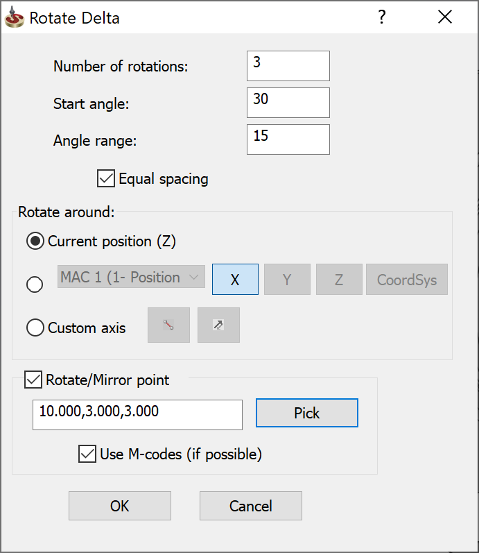
Rotate Delta parameters
- Number of rotations: Set how many times the operation tool path is rotated.
- Start angle: Enter the start angle (+/-) relative to the positive X-axis.
Angle step: Angle step is enabled when the Equal spacing check box is disabled. Enter the delta value (+/-) between two rotation steps.
Angle range: Enter the total angle value between the start angle and the end angles when using the Equal spacing option. Equal spacing enables you to define the angle range between the first and the last translated operations, instead of defining the incremental angle. The angle step is calculated automatically as a result of dividing the Angle range value by the Number of rotations value.
Rotate around
Define the axis around which the operation is rotated using the following methods:
- Current position (Z) – rotates the operation around the Z-axis of the current Coordinate System passing through a defined point. To define the point, select the Rotate/Mirror point option, click Pick and pick the point directly on the solid model. You can also enter the point coordinates in the text field.
- MAC – rotates the operation around the cooresponding axis (X, Y, Z) of an existing Coordinate System position. Select an existing Coordinate System from the list or define a new position by clicking the Coordsys button to display the Coordsys Manager dialog box.
- Custom
axis – rotates the operation relative to any chosen axis, sketch
element or model edge. The
 button enables
you to pick the axis directly on the solid model. The
button enables
you to pick the axis directly on the solid model. The  button enables you to reverse
the direction of the custom axis and the direction of rotation.
button enables you to reverse
the direction of the custom axis and the direction of rotation.
- Optionally, you can define the point about which the operation is mirrored by using the Rotate/Mirror point option. Click Pick and pick the point directly on the solid model. You can also enter the point coordinates in the text field.
List
This option rotates the operation tool path to a list of angle locations defined by their angle relative to the positive X-axis.
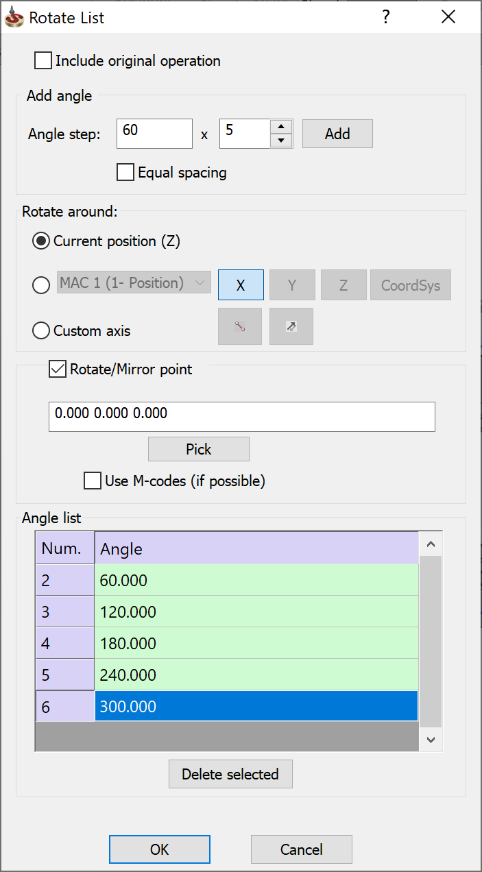
Include original operation
Select this check box if you want to include the original operation in the transforming action.
Add angle
Angle step: Angle step is enabled when the Equal spacing check box is disabled. Enter the delta value (+/-) between two rotation steps.
Angle range: Enter the total angle value between the start angle and the end angles when using the Equal spacing option. Equal spacing enables you to define the angle range between the first and the last translated operations, instead of defining the incremental angle. The angle step is calculated automatically as a result of dividing the Angle range value by the number of rotations.
Enter the Angle step or Angle range value.
Enter the number of rotations.
Click Add to calculate and add the operations to the Angle list.
Confirm with OK.
Rotate around
Define the axis around which the operation is rotated using the following methods:
Angle list
Editing angles
Double-click the entry in the Angle column.
Enter the new value.
Deleting angles
Select the entry in the Angle list.
Click Delete selected.