Constraint Boundaries
SolidCAM enables you to define the constraint boundaries. A constraint boundary enables you to limit the machining to specific model areas.
Machining always takes place within a boundary or a set of boundaries. The boundaries define the limits of the tool tip motion. The area actually machined can be extended beyond the boundary by as much as the tool shaft radius.
Boundary type
|
You must first select the Use constraint boundaries check box to enable the available boundary parameters. |
The following boundary types are available:
This option enables you to automatically create the boundary using the stock or target models.
The following types of automatically created boundaries are supported in SolidCAM:
Created Automatically - 3D Boundaries
SolidCAM enables you to automatically create 3D Boundaries using Part Silhouette. The area which will be machined by the tool is limited to the tool center line which follows exactly the actual part shadow.

This option enables you to manually create the boundary using the stock or target models.
The following types of manually created boundaries are supported in SolidCAM:
Boundary name
This section enables you to define a new boundary geometry or choose an already defined one from the list. This section is enabled after selecting the Created manually option.
New
 displays the appropriate dialog box for the geometry definition.
Edit
 displays the Geometry
Edit dialog box enabling you to choose the chains for the boundary.
The chosen boundaries are displayed and highlighted in the graphic
window.
displays the Geometry
Edit dialog box enabling you to choose the chains for the boundary.
The chosen boundaries are displayed and highlighted in the graphic
window.
Tool-boundary relation
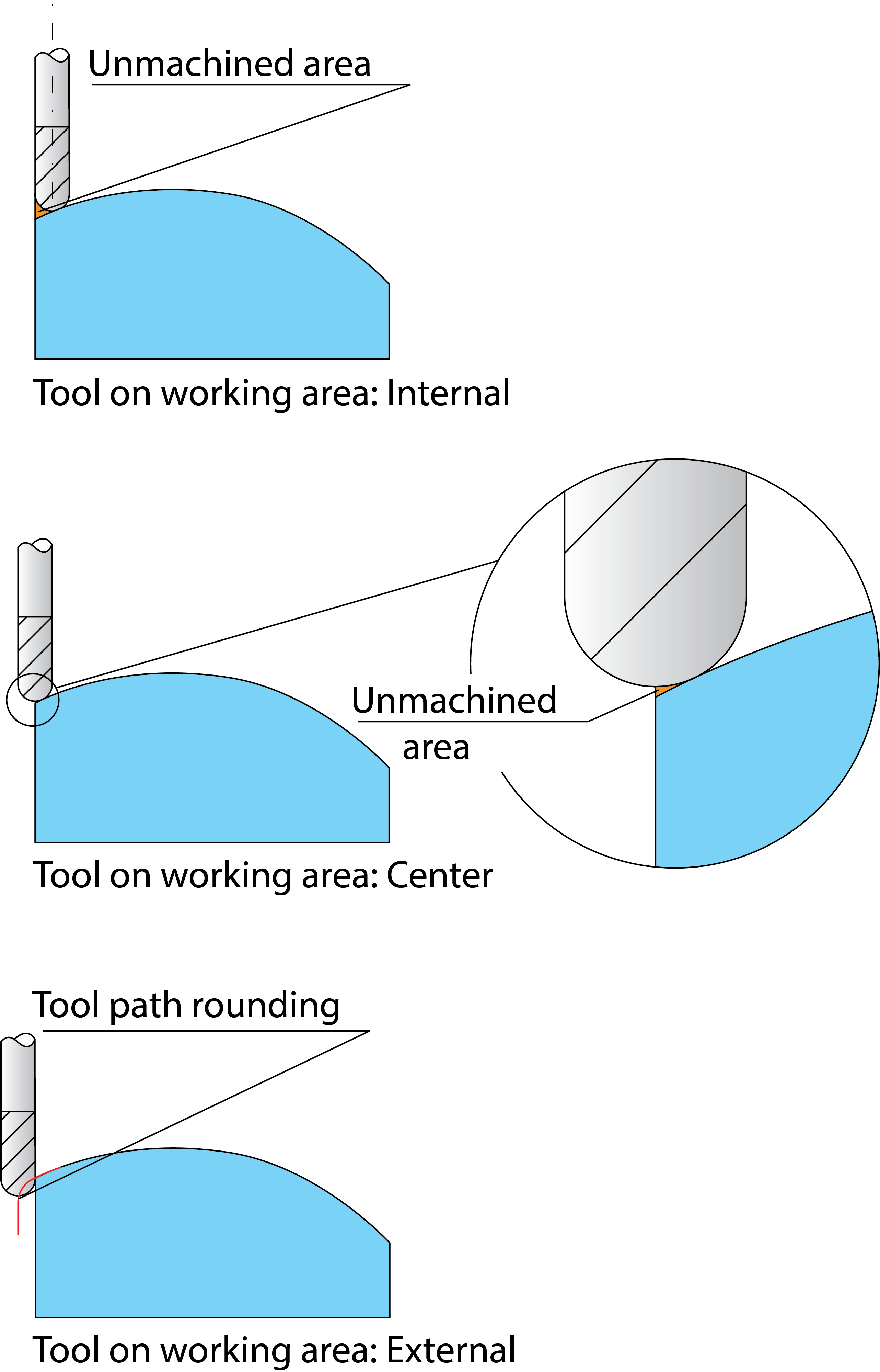
This option controls how the tool is positioned relative to the boundaries. This option is relevant only for 2D boundaries.
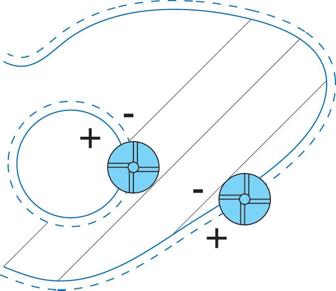
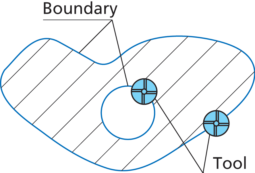
External The tool machines outside the boundary. |
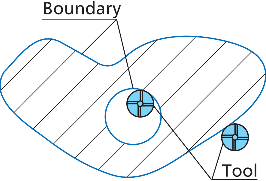 |
Internal The tool machines inside the boundary. |
 |
Center The tool center is positioned on the boundary.
|
 |
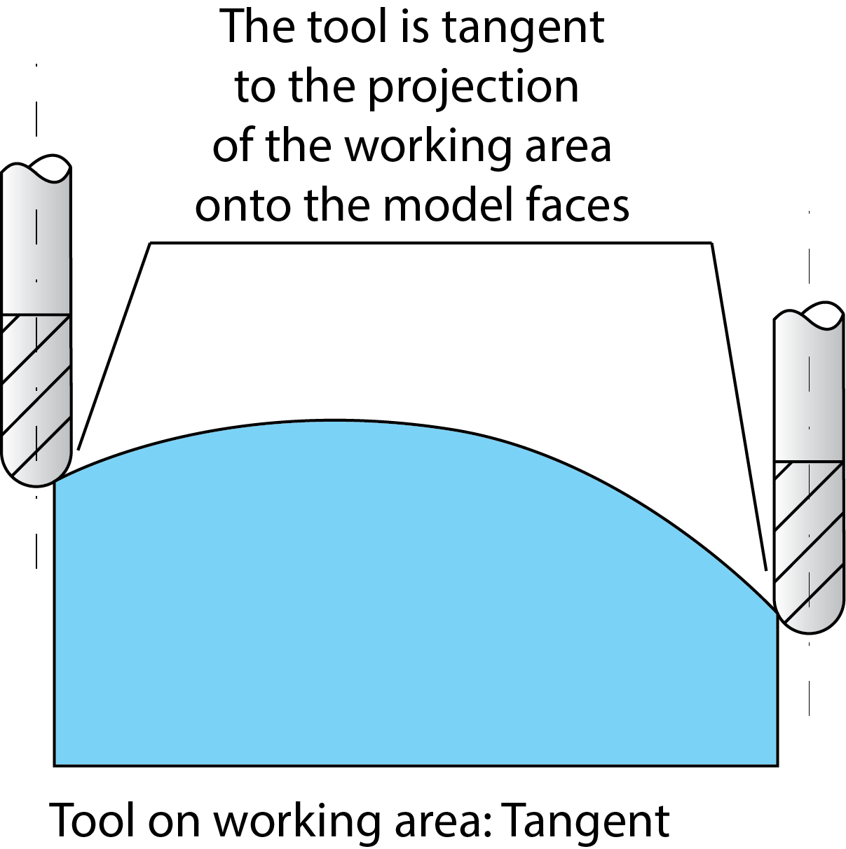
Tangent The Internal/External/Centered methods of the boundary definition have several limitations. In some cases, the limitation of the tool path by planar boundary results in unmachined areas or corners rounding.
The Tangent option enables you to avoid these problems. When this option is chosen, SolidCAM generates the tool path boundaries by projecting the planar working area on the 3D model. The tool path is limited in such a way that the tool is tangent to the model faces at the boundary. This option enables you to machine the exact boundary taking the geometry into account.
|
 |
Show button displays the selected Constraint boundaries on the solid model.
This value enables you to specify the offset of the tool center. A positive offset value enlarges the boundary; a negative value reduces the boundary to be machined.