Geometry Definition
The Target geometry section enables you to specify the appropriate Coordinate System for the operation and to define the machining geometry.
CoordSys
SolidCAM enables you to define the Coordinate System for the operation by choosing it from combo-box or by selecting it from the graphic screen by clicking CoordSys. The CoordSys Manager dialog box is displayed. Together with this dialog box, SolidCAM displays the location and axis orientation of all Coordinate Systems defined in the CAM-Part.
To get more information about the Coordinate System, right-click the CoordSys entry in CoordSys Manager and choose the Inquire option from the menu.

The CoordSys Data dialog box is displayed.
When the CoordSys is chosen for the operation, the model is rotated to the appropriate orientation.
The CoordSys selection operation must be the first step in the geometry definition process.
Machining surfaces
After the Coordinate System is chosen, define the 3D Model geometry for the SolidCAM Turbo 3D HSM operation. The Machining surfaces are the entire model or any surface(s) of the design model.
If you have already defined 3D Model geometries for this CAM-Part, you can select a geometry from the list.
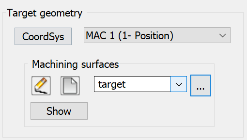
Show displays the chosen 3D model geometry in the SOLIDWORKS window.
![]() enables you to define a new
3D Model geometry for the operation with the 3D
Geometry dialog box.
enables you to define a new
3D Model geometry for the operation with the 3D
Geometry dialog box.
|
When you choose the geometry from the list, the related Coordinate System is chosen automatically. |