Clearance data
The Clearance data tab enables you to define the clearance offsets for arbor and tool holder in order to get a guaranteed clearance gap between arbor, tool holder and workpiece.
Clearance
SolidCAM enables you to choose either Cylindric or Conical shape of the tool holder, arbor and tool shaft clearance.
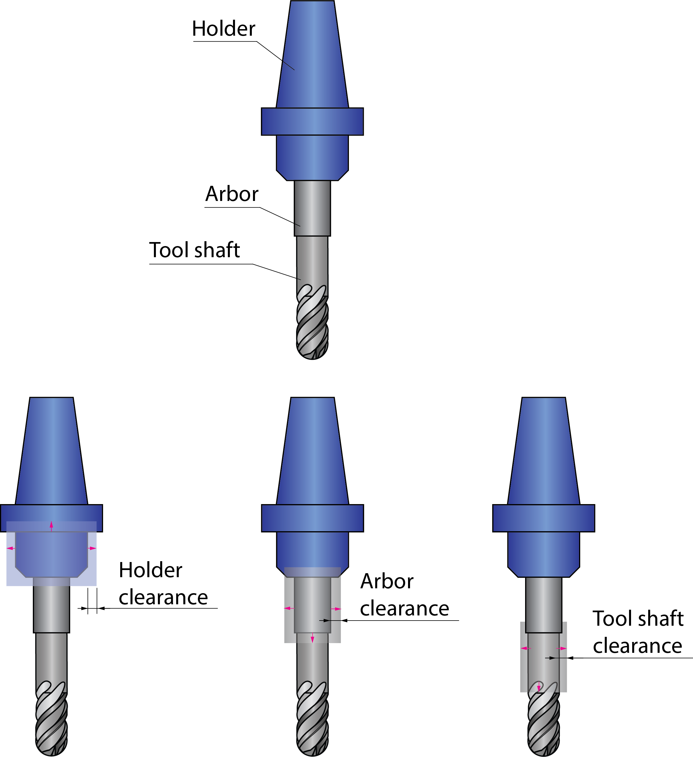
Cylindric clearance
![]()
The Holder parameter defines the offset applied to the tool holder cylinder from all sides.
The Arbor defines the offset applied to the arbor cylinder from all sides.
The Tool Shaft parameter defines the offset applied to the tool shaft cylinder from all sides.
The Angular parameter defines the angular offset applied to the tool.
|
Generally, an arbor is the tool extension located between the tool shaft and its holder. Lollipop and Slot End Mills do not have tool shaft, the cylindrical Connection between tool and holder is considered as Arbor.
|
Conical clearance
Conical clearance is applied similarly to the cylindrical one being defined with Upper and Lower offset values.
![]()
Angular conical clearance is applied between the tool and collision surface. It is spanned between the contact point of the tool, the drive surface, and the collision point.
|
The Upper offset value must be greater than the Lower offset value. |
Air move safety distance
![]()
This parameter enables you to define the minimal distance between the clearance area and the Drive surface.
The Advanced tab enables you define the Advanced parameters of Clearance data.
Report remaining collisions
This option enables you to generate a report about possible collisions that remain in the tool path after gouge checking. When this option is selected, SolidCAM checks the tool path using the tolerance two times greater than the specified value to detect collisions.
|
You can turn off the collision checking between the tool path positions. In such case the tool path calculation is accelerated, but the possibility of remaining collisions is present. The Report remaining collisions option is helpful to notify about possible collisions in the resulting tool path. In case of engraving or trimming operations used together with the Report remaining collisions option, SolidCAM notifies you about collisions. The reason for such notification is that the technology of such operations requires that the tool tip be inside the machined surfaces. The Report remaining collisions option enables you to detect too small retract and approach distances or too low clearance levels. In such case, the report about collisions enables you to solve the potential problems. |
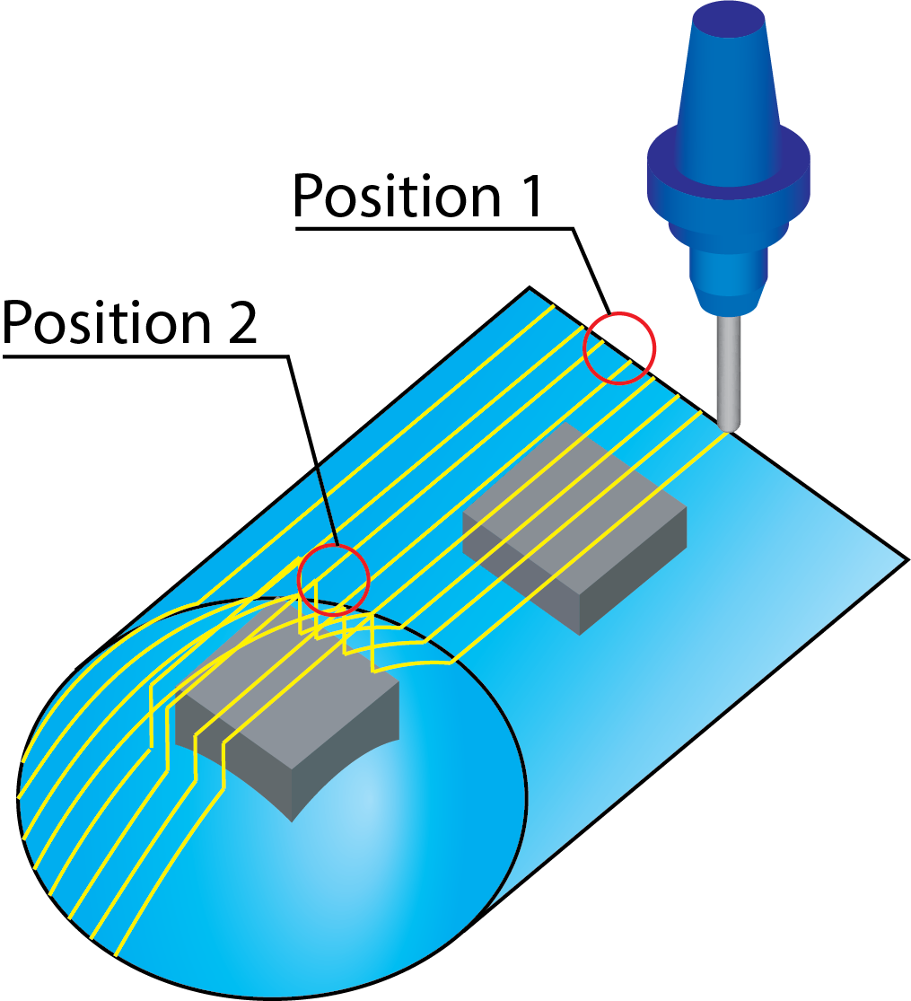
Check gouge between positions
The Check gouge between positions option enables you to avoid the possible gouges between tool path positions. When the movement is performed between two successive tool path positions, this option enables you to check for possible collisions of the tool and tool holder with drive and check surfaces.
|
This option is useful especially for flat faces machining, where the tool path positions are generated only at the drive surface edges. |
| When the Check gouge between positions option is not used, the gouge checking of the tool path on the flat face is not performed because of absence of tool path positions on the face. The gouging of a boss may occur. | When the Check gouge between positions option is used, the gouge checking between tool path positions on the flat surface is performed. The gouging of a boss is avoided. |
|
|
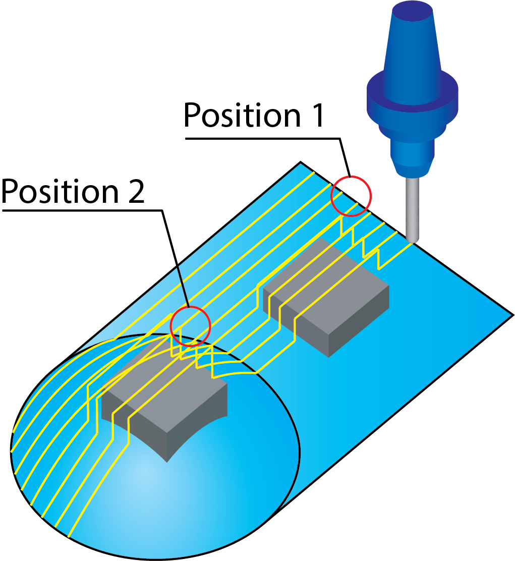
The Check gouge between positions option has no effect on the gouge checking of the tool path spherical surface, because of the many tool path positions that were generated on this face. The gouge checking for this face is performed for these positions avoiding possible collisions.
Extend tool to infinity
This option enables you to consider the tool as being extended to infinity during collision check in order to make sure that all active surfaces are checked for collision, no matter where they are located in space.
Check link motions for collisions
When this option is chosen, SolidCAM automatically performs the gouge checking for link movements in order to avoid possible collisions.
Trim contour for safe retract
Selecting the Trim contour for safe retract enables the tool to retract without any collisions. This check box is available only when Check link motions for collision check box is selected.
Check link motions against boundaries
Selecting the Check link motions against boundaries ensures that direct and blend spline links remain within the constraint boundaries and in case the tool path has to cross cut the constraint boundaries the links be replaced with the clearance area linking.
Enabling this option allows you to select one of the following:
Active boundaries- This can be constraint boundaries and/or Silhouette boundaries.
|
Check link motions against boundaries works only with Constraint boundaries. If Use Constraint boundaries option is unchecked SolidCAM displays an error.
|
Other curves- A user-defined curve.
Boundary name
This section is enabled after selecting the Other curves option. This section enables you to define a new boundary geometry or choose an already defined one from the list.
 New displays the appropriate dialog
box for the geometry definition.
New displays the appropriate dialog
box for the geometry definition. Edit
displays the Geometry Edit dialog
box enabling you to choose the chains for the boundary. The chosen
boundaries are displayed and highlighted in the graphic window.
Edit
displays the Geometry Edit dialog
box enabling you to choose the chains for the boundary. The chosen
boundaries are displayed and highlighted in the graphic window.Show displays the Show Geometry dialog box and the boundaries are displayed and highlighted in the graphic window.
 displays the list of geometries
that can be selected as a new boundary.
displays the list of geometries
that can be selected as a new boundary.
Offset- This option is enabled after selecting the Other curves option. The offset section enables you to apply an additional positive or negative offset value to the defined boundary.
Related Topics