Working area definition via Face selection
You can define the area of the 3D Model machining with two sets of model faces:
Drive faces – the set of faces to be milled. The tool path is generated only for machining of these faces.
Check faces – the set of faces to be avoided during the generation of the tool path.
Other faces of the model are not considered during the tool path calculation.
Example:
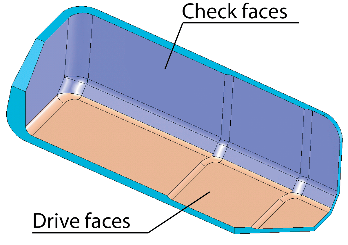
For the model shown above, SolidCAM generates the tool path only for the shallow area. During the calculation, gouging of the check faces is avoided. The remaining faces do not participate in the tool path calculation.
The above capability is available through the Work on selected faces area in the Working Area dialog box.
Drive faces
Specify the Face geometry for Drive faces. If you have already defined such geometries for this CAM-Part, you can choose the geometry from the Name list.
Define enables you to define a new Face geometry with the Select Faces dialog box.
Show displays the Face geometry on the SOLIDWORKS model.
Check faces
Specify the Face Geometry for Check faces. If you have already defined such geometries for this CAM-Part, you can choose the geometry from the Name list.
Define enables you to define a new Face geometry with the Select Faces dialog box.
Show displays the Face geometry on the SOLIDWORKS model.
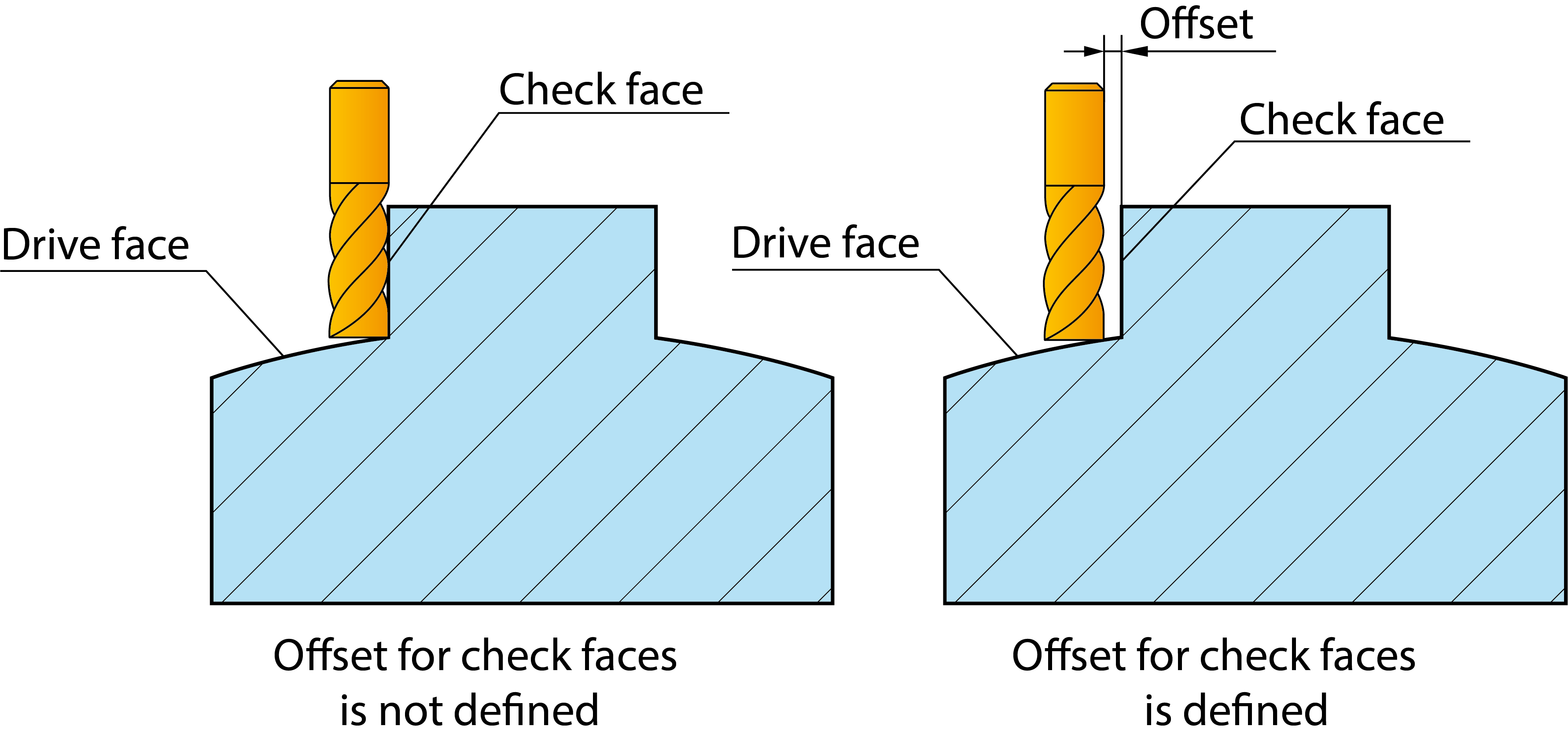
SolidCAM enables you to specify the Offset for the check faces when machining is performed on selected faces. Using this offset, SolidCAM enables you to perform the machining at a safety distance from the check surfaces.
Related Topics