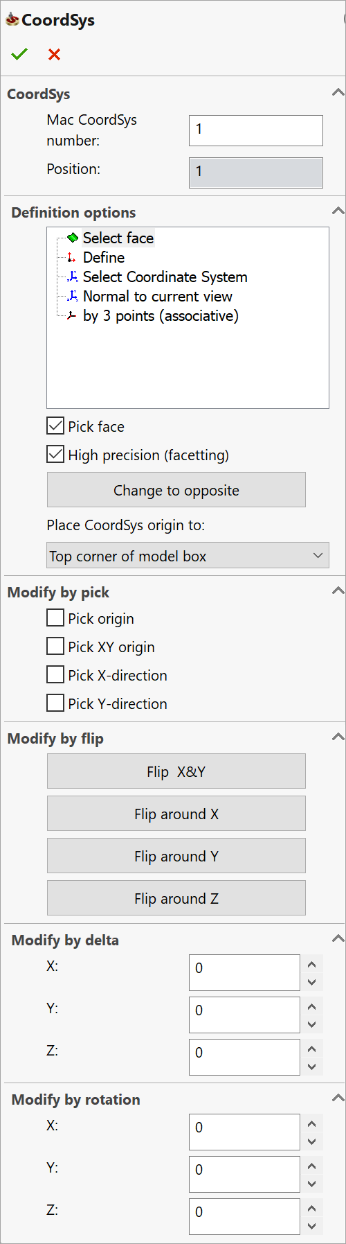
CoordSys dialog box
This dialog box enables you to define a new Coordinate System directly on the solid model. The newly created Coordinate System automatically receives the next sequential number.
When you accept the Coordinate System by clicking ![]() , the model is rotated to
isometric view if the option to auto-rotate the model in Coordsys Manager
is selected in the SolidCAM
Settings.
, the model is rotated to
isometric view if the option to auto-rotate the model in Coordsys Manager
is selected in the SolidCAM
Settings.
Mac CoordSys number – this number corresponds with the built-in controller functions (for example, G54, G55, etc. in the Fanuc type controllers). It can be used for different clamping positions (Machine Coordinate Systems) in different operations on the CAM-Part.
Position – this number defines the sequential number of the CoordSys. For each Machine Coordinate System (Mac CoordSys), several Positions are defined for different positionings; each such Position is related to the Machine CoordSys.
|
|
Definition options
SolidCAM enables you to define the Coordinate System by one of the following methods:
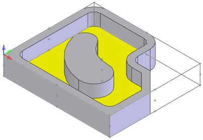
Select face
When you define the Coordinate System by selecting a face, the box surrounding the model is calculated. For this box, SolidCAM generates a number of sketch points to facilitate the CoordSys definition. The points are located in the box corners, in the middle of each edge and in the centers of the planes (in the intersection point of the diagonals). The box is then added to the model as a 3D sketch.
The face can be one of the following:
Planar face
The Z-axis of the Coordinate System is normal to the selected face.
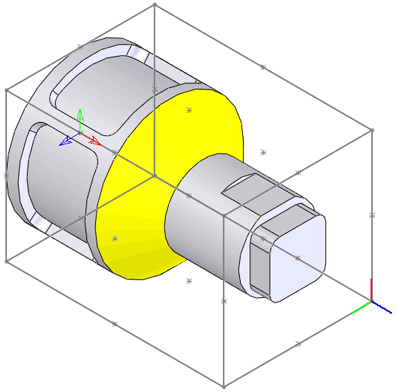
Cylindrical/Conical face
The Z-axis of the Coordinate System is parallel to the axis of revolution of the specified cylindrical/conical face.
Selecting this check box enables you to pick a face on the model for the Coordinate System definition. The selected model face is highlighted.
High precision (facetting)
When this check box is selected, the Coordinate System is defined using the faceted model, which results in more precise definition but may take more time to generate.
|
The facetting tolerance value is defined on the Coordsys definition page of the SolidCAM Settings dialog box. |
When this check box is not selected, the Coordinate System is defined using SOLIDWORKS tools without facetting.
The default state of the check box for new parts can be defined in SolidCAM Settings.
Change to opposite/Change to original
This button enables you to reverse the direction of the Coordinate System Z-axis.
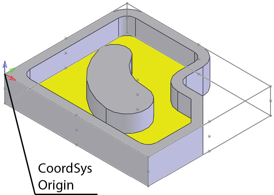
The upper plane of the model box is parallel to the XY-plane of the defined CoordSys.
The CoordSys is located in the corner of the model box with the following coordinates (XMIN, YMIN, ZMAX).
The lower plane of the model box is parallel to the XY-plane of the defined CoordSys.
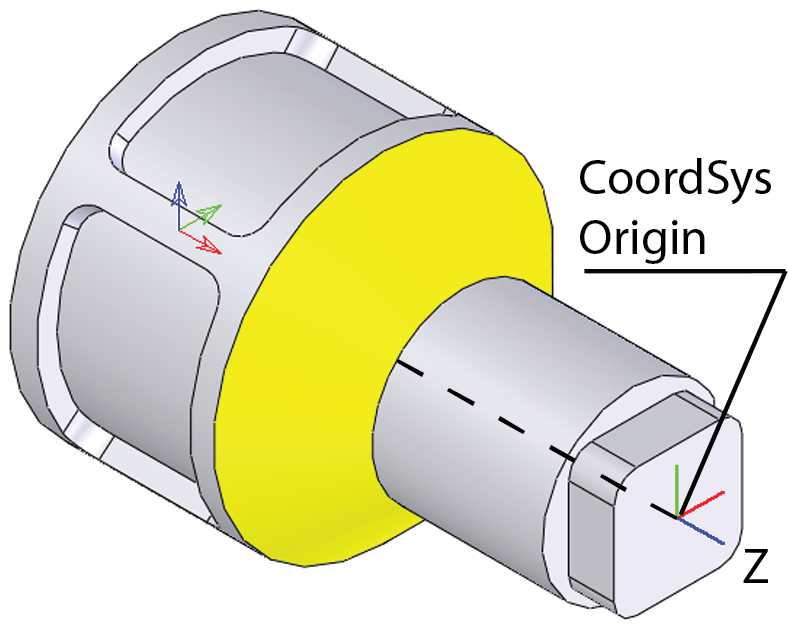
The origin is located at the intersection of the rotation axis of the part and the face of the model box with the maximal Z-coordinate (the Z-axis is directed along the rotation axis).
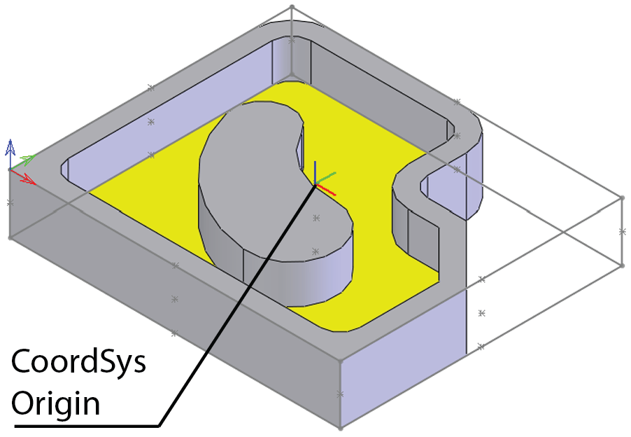
The CoordSys origin is placed in the center of the upper plane of the model, and the Z-axis of the CoordSys is normal to the selected face.
Bottom center of model box
The CoordSys origin is placed in the center of the lower plane of the model, and the Z-axis of the CoordSys is normal to the selected face.
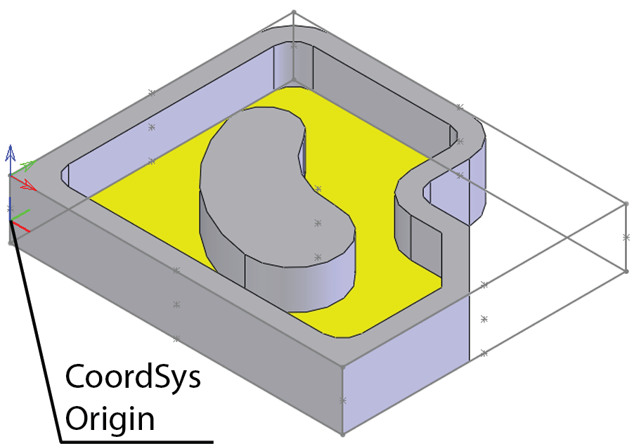
The CoordSys origin is placed in the corner of the generated model box on the same Z-level with the selected face, and the Z-axis of the CoordSys is normal to the selected face.
CoordSys # 1
The CoordSys position is automatically placed at the position of Machine CoordSys #1.
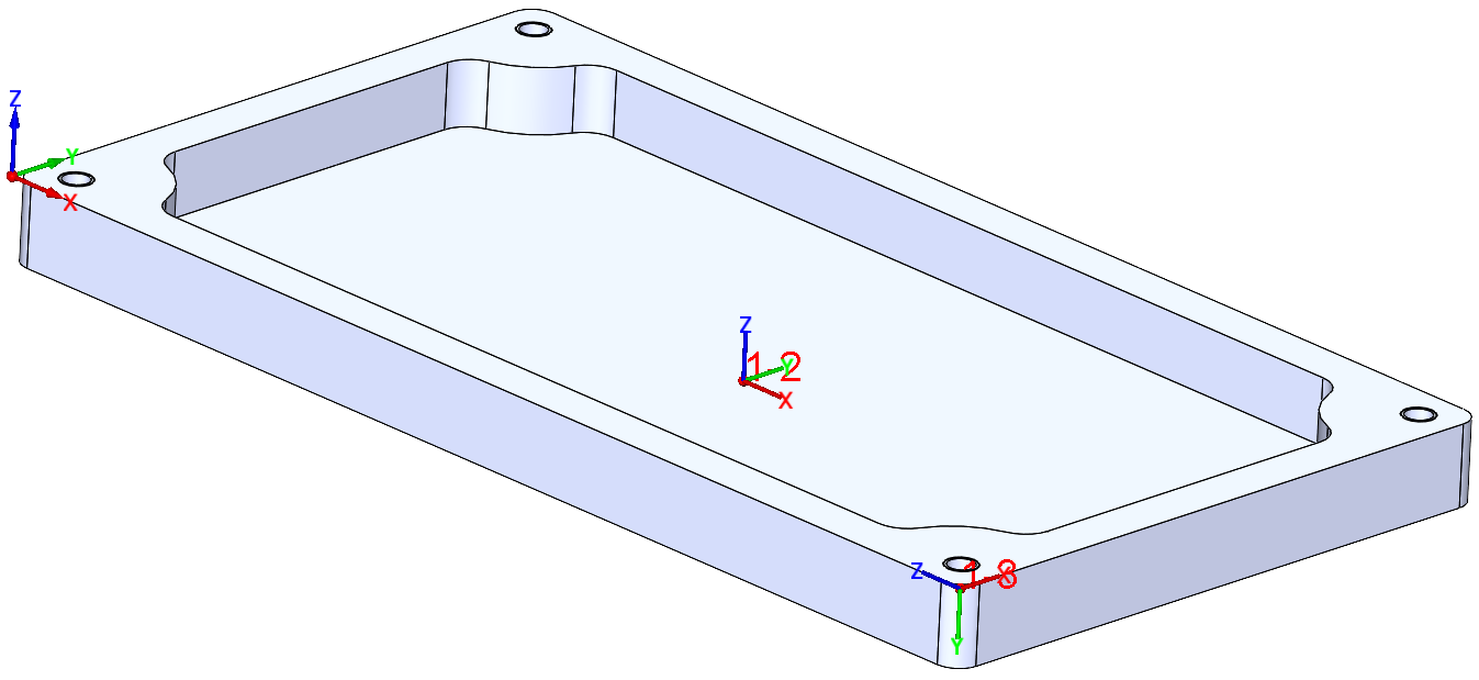
Define
This option enables you to define the CoordSys Origin and axes by selecting points.
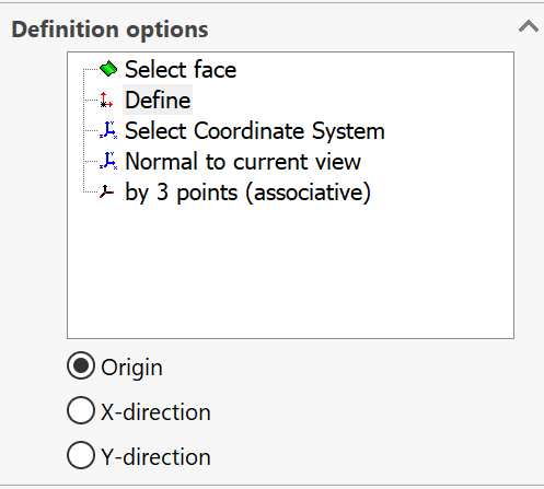
Select the origin point on the graphic screen.
X-direction
Select a point relative to the origin that defines the X-axis.
Y-direction
Select a point that defines the plane (the Y-axis is 90 degrees to the X-axis; the selected point defines the plane).
|
After a point has been selected, the next button is automatically activated. If you miss the selection, you can at any time click the required button and continue automatically to the next button. |
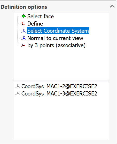
Select Coordinate System
SolidCAM enables you to choose the coordinate system defined in the CAD model file as the SolidCAM Coordinate System. SolidCAM keeps the CAM coordinate system associative with the chosen CAD coordinate system. |
 |
Normal to current view
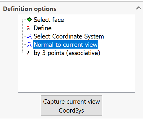
This option enables you to define the Coordinate System with the Z-axis normal to the model view you are facing on your screen. You may bring the model to the desired orientation by using the CAM Views toolbar or just rotate it in an arbitrary fashion; then click the Capture current view CoordSys button, and the Coordinate System will be generated relative to the model view you are using. The CoordSys origin will lie in the origin of the SOLIDWORKS Coordinate System, and the Z-axis will be directed normally to the chosen view of the model.
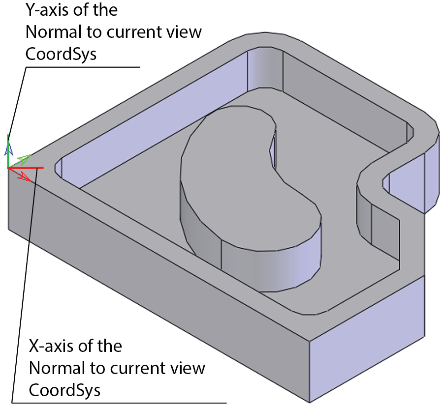
You may change the location of the CoordSys using the placing options of the Select face mode, and then choose the Normal to current view mode to adjust the directions of the axes to the current model view.
By 3 points (associative)
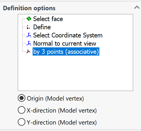
This option enables you to define the CoordSys Origin and axes by selecting any three points.
- Origin (Model vertex)
Select the origin point on the graphic screen.
X-direction (Model vertex)
Select a point relative to the origin that defines the X-axis.
Y-direction (Model vertex)
Select a point relative to the origin that defines the Y-axis.
Editing the Coordinate System
After the face has been selected, you can edit the Coordinate System location by picking entities on the model and change the directions of its axes.
Modify by pick
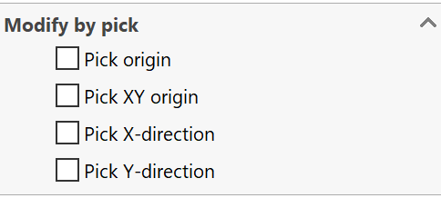
This option enables you to define a new location for the CoordSys origin. The direction of the axes is not changed.
This option enables you to define a new location for the CoordSys origin in the XY-plane by picking a point on the model. The Z-level of the CoordSys origin and the directions of the axes remain the same.
This option enables you to choose a new direction for the X-axis by picking a point on the model.
This option enables you to choose a new direction for the Y-axis by picking a point on the model.
Modify by flip
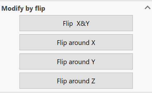
click this button to rotate the Z-axis 180 degrees by mutual replacement of the X- and Y-axes (X becomes Y, and Y becomes X).
This button rotates the CoordSys 90 degrees around the X-axis.
This button rotates the CoordSys 90 degrees around the Y-axis.
This button rotates the defined CoordSys 90 degrees around the Z-axis.
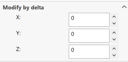
Modify by delta
This option enables you to move the CoordSys origin in the X-, Y-, and Z-coordinates relative to the point in which it was previously defined.
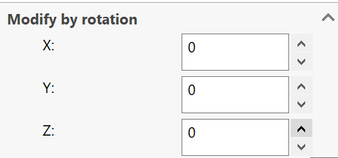
Modify by rotation
This option enables you to rotate the defined CoordSys a given number of degrees around the X-, Y- and Z-axes, but the rotation can only be defined around each axis separately. You cannot rotate the CoordSys around more than one axis simultaneously.