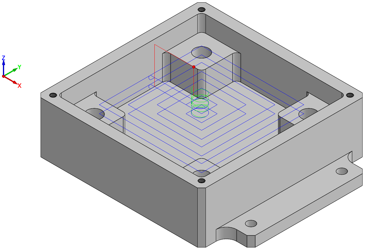
Host CAD simulation mode
This simulation mode enables you to display the tool path directly on the model in the SOLIDWORKS window. Since all the View options of SOLIDWORKS are active during the simulation, you can see the tool path from different perspectives and zoom to various areas of the model.
|
|
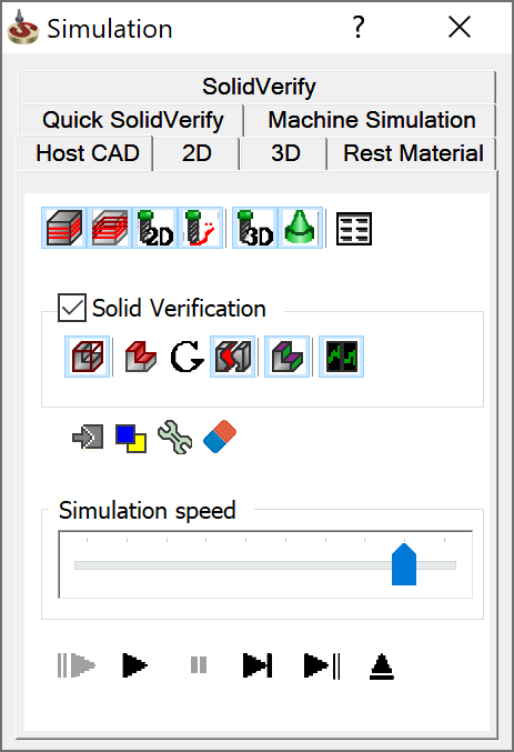
Simulation control panel
The Simulation control panel offers you the following controls to manage the simulation:
Show Tool path
This option toggles on/off the tool path for the current operation.
Show hidden lines 
This option toggles on/off the display of tool path lines hidden by the model geometry.
When this option is selected, the hidden lines are visible on the model.
When this check box is not selected, the hidden lines are not visible on the model.
Show tool 2D 
This option toggles on/off the graphic simulation of the tool.
Show trail 
This option displays several previous elements of the tool path by highlighting them with a different color. The color is defined in the Simulation settings.
Show tool 3D 
This option toggles on/off the 3D graphic simulation of the tool.
Show holder 
This button toggles the display of the tool holder during simulation. The option is enabled only with Show tool 3D.
Show
data 
Select this check box to display tool path information such as coordinates of the current point, time, feed in the Simulation Data dialog box.
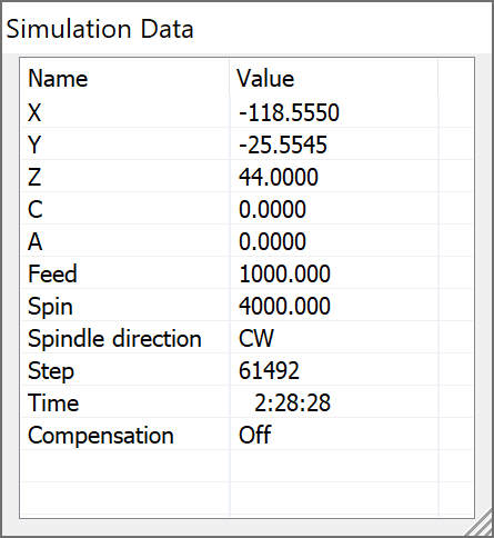
The X, Y, and Z fields display the position of the tool relative to the CoordSys at every step of the simulation.
Feed displays the current feed rate.
Spin displays the current spin rate.
Spindle direction displays the Clockwise(CW) or Anticlockwise (CCW) direction of the spindle. In Multi-depth drilling operations, when the spin direction is set to OFF this field is empty.
The Step field displays the number of steps of the simulation.
Time shows the elapsed machining time of the simulated operations (theoretical value based on feed and distance covered).
Compensation displays whether Compensation is defined in the Technology page.
Solid Verification
These options enable you to display machining simulation on the solid model similar to SolidVerify using the SOLIDWORKS model.
Show
Stock 
This option displays how the stock is updated during the simulation.
Show
rest material 
This option uploads the target model and highlights the areas with left material. The highlighting color is defined in the Simulation settings.
Show
gouges ![]()
This option displays the gouge report.
Enable
automatic stock splitting 
This option toggles on/off the automatic splitting of the stock.
Colorize
stock 
This option enables you to display the updated model surfaces in the same color as the tool's color.
Multi-Core
support 
This option enables you to perform multicore calculation of the simulation. It means that the CPU performance of your computer is optimized in such a way that allows simultaneous calculation of different elements by different central processing units (cores). In this case, the animation is faster, but looks less accurate.
Stop on next
This option opens the Stop on Next dialog box where you can define the specific point to stop the simulation process.
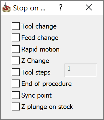
The options of this dialog box are following:
Tool change - this option stops the simulation every time when the tool changes.
Feed change - this option stops the simulation every time when the feed changes.
Rapid motion – this option stops the simulation every time when the rapid motion is performed.
Z Change - this option stops the simulation at every change of the Z coordinate of the tool.
Tool steps - this option stops the simulation every defined number of tool steps.
End of procedure - this option stops the simulation at the end of the procedure.
Sync point - this option stops the simulation of the balanced roughing turning, when one tool waits for another in a synchronization point.
Z plunge on stock - this option pauses the simulation when tool plunges in the Z direction in rapid motion and comes in contact with the stock.
Clear 
This button clears the simulated tool path and the tool images from the Host CAD screen.
Colors 
Click Colors to change the display color of the simulated tool path. The Simulation Colors dialog box is displayed.
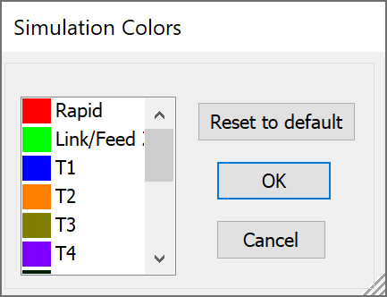
- To change the tool color, click the colored box next to the tool number.
- The standard color dialog box of Windows will be displayed.
- Select the new tool path color for this tool number.
- Confirm with OK.
|
You can use the Reset to default to apply the default tool colors defined in the SolidCAM Settings dialog box. |
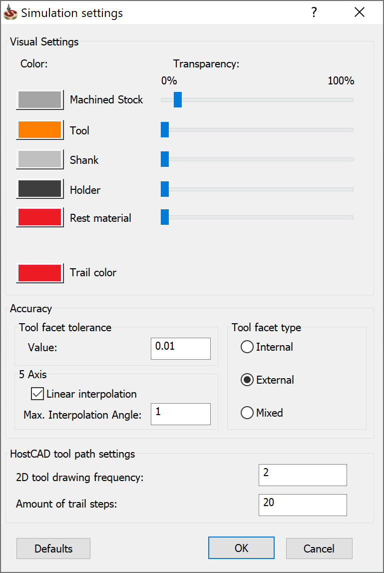
Settings
Clicking the Settings
This section enables you to define the color and transparency level for various model elements: Machined Stock, Tool, Shank, Holder, and Rest Material. You can also set the trail color. This section enables you to define the type and tolerance value of the tool facet used in Solid Verification. The 2D tool drawing frequency field defines the number of steps between showing the tool position. The Amount of trail steps value defines the number of tool path lines that are marked as trail. |
 |