Automatic CoordSys Positions definition
SolidCAM automatically defines CoordSys Positions related to the Machine CoordSys suitable to machine Machinable Hole Features of a specific Feature Set. The CoordSys Position is created according to the following data:
The Machine CoordSys used in the Feature Set;
The Axis type of the Feature Set;
The Direction of the Machinable Hole Feature.
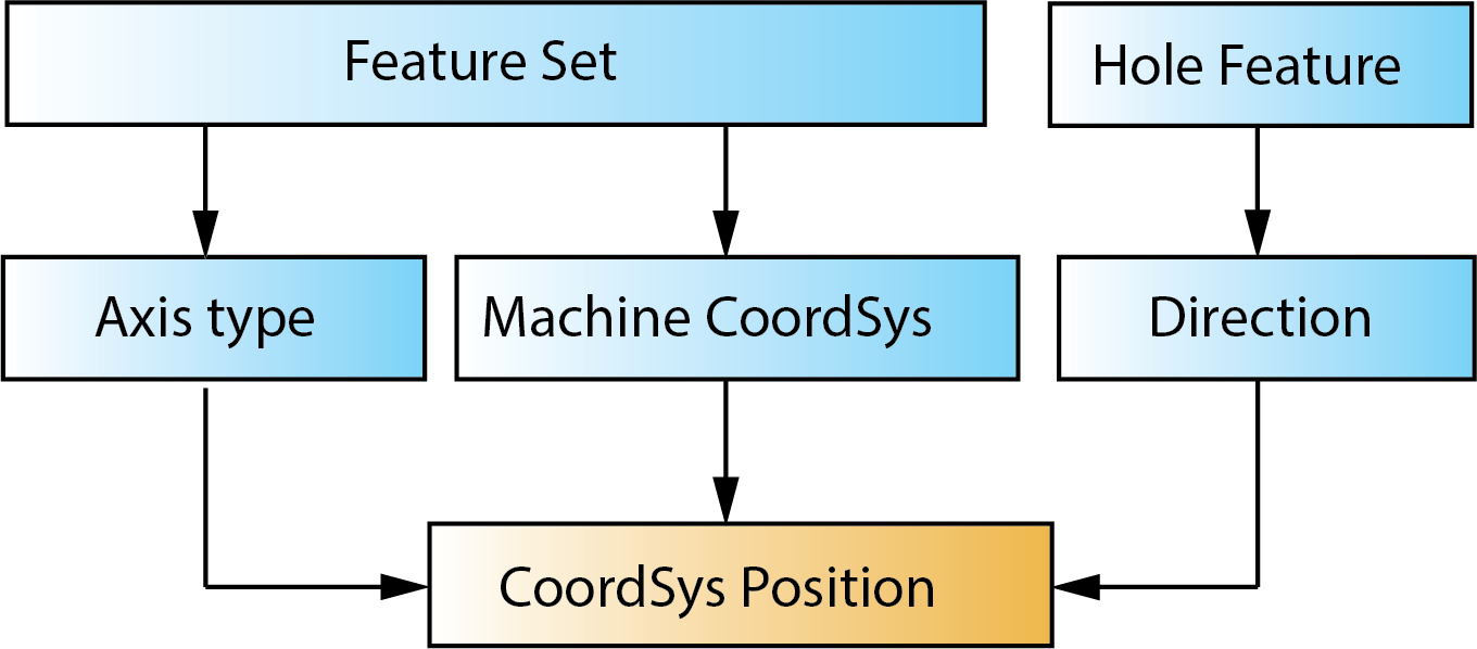
The Z-axis of the defined CoordSys Position is coincident with the Machinable Hole Feature direction. The direction of the X- and Y-axis is defined according to the Machine CoordSys and Axis Type.
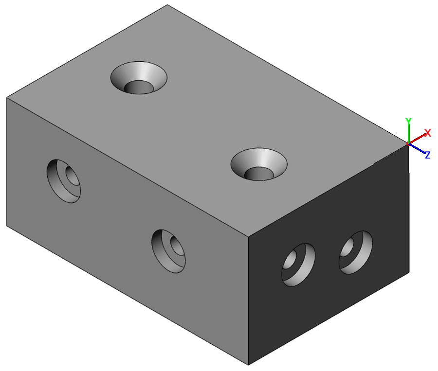
When the Machinable Hole Feature is accepted by the Compatibility Checker, SolidCAM compares the direction of the Machinable Hole Feature with the Z-axis of the existing CoordSys Positions related to the Machine CoordSys of the Feature Set. If the direction and Z-axis of the CoordSys Position are parallel, the Hole Feature will be assigned to the CoordSys Position. If a suitable position is not found, SolidCAM defines a new one.
SolidCAM enables you to automatically locate the origin of the created CoordSys Position in dependence of the Hole Recognition Settings. The origin of the CoordSys Position can be placed in the following locations:
The CoordSys position is placed in the position of Machine CoordSys #1
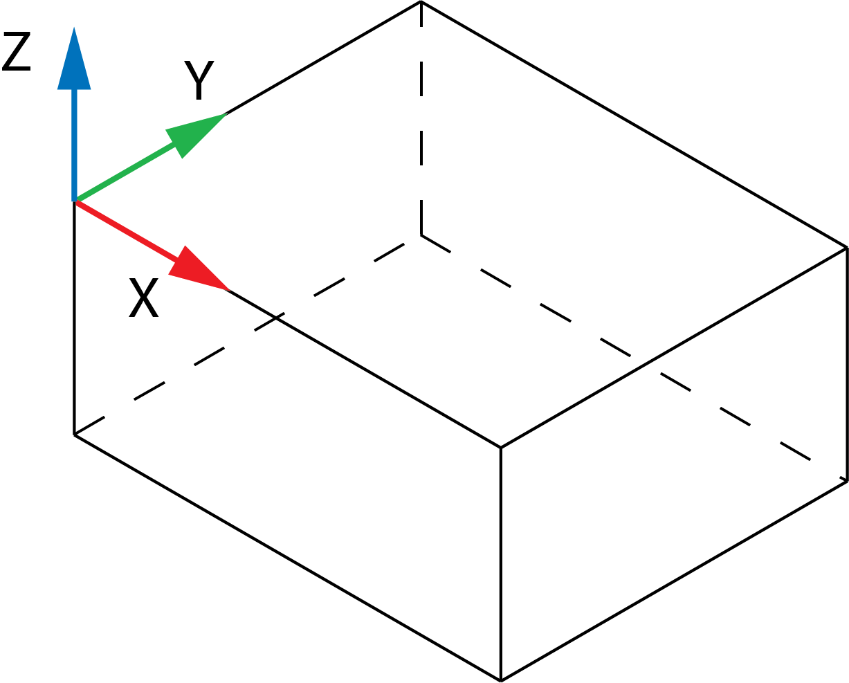
The CoordSys position can be placed in the corner of the model box.
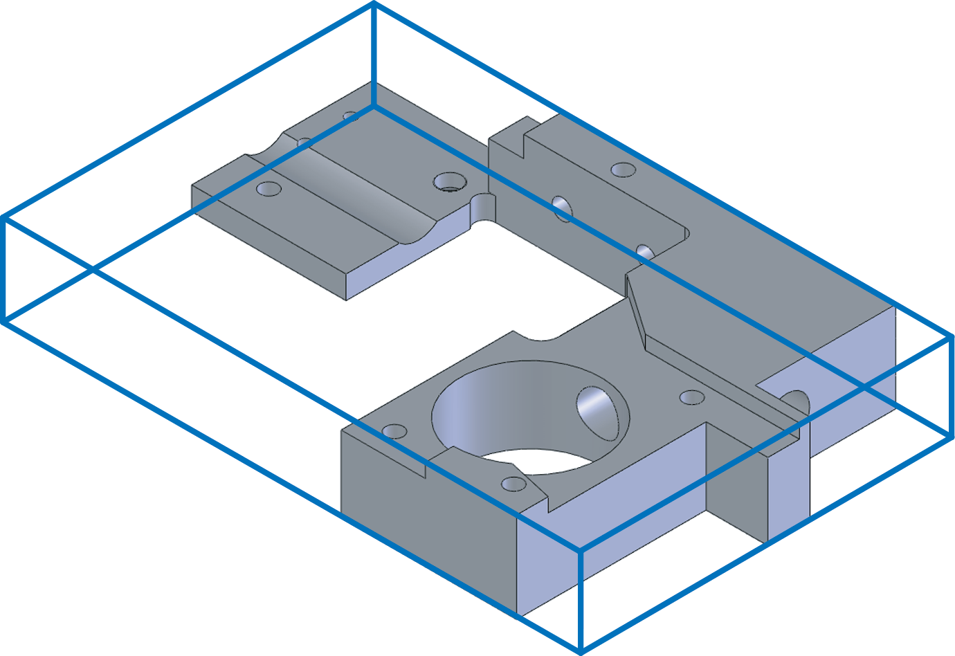
SolidCAM calculates the box surrounding the model (model box) in the coordinate system of the first Machine CoordSys.
The CoordSys Position will be located in the corner of the model box with the following coordinates (XMIN, YMIN, ZMAX).
Related Topics