Adaptive step down parameters
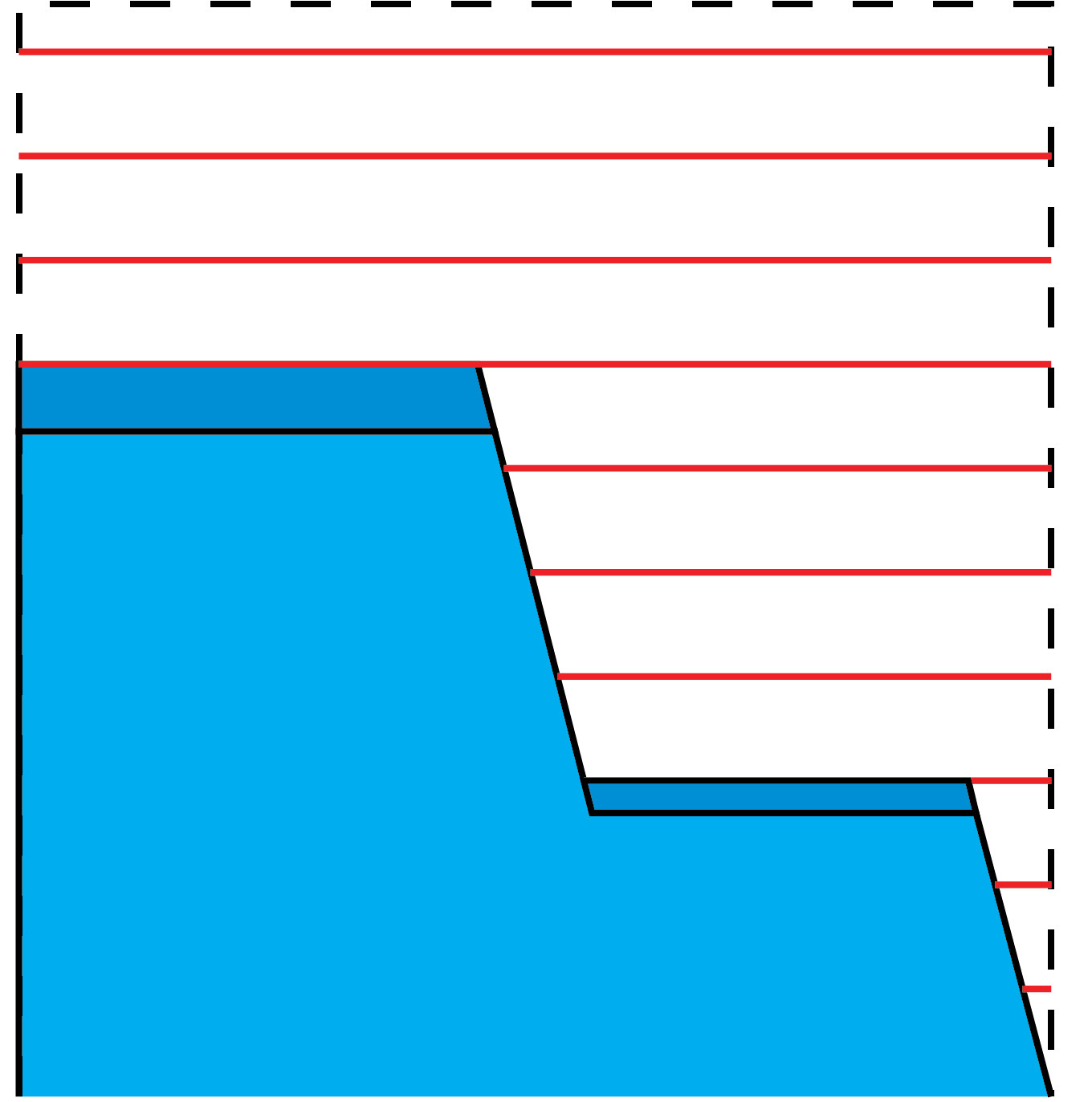
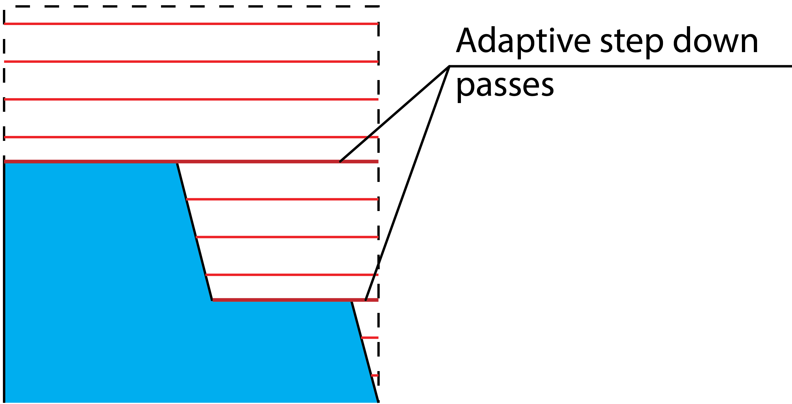
In areas where the horizontal distance between the passes is significant, Adaptive Step down can be used to insert extra passes and reduce the horizontal distance.
In areas where the passes on the topmost edges of a surface would fall too close or too far away from that edge, Adaptive Step down adds extra passes to compensate. So the Step down value controls the maximum Z-distance between the passes for the entire surface, while Adaptive Step down adjusts those values for best fitting the surfaces.
Optimize Z level
This option enables you to adjust slightly the Z-distance between passes in order to avoid surfaces which are approximately horizontal. These approximately horizontal surfaces can cause severe fragmentation of the cutting level.
Last levels to even
To avoid a situation when the tool takes a very shallow cut for the last level, you can define a number of last cuts that will be averaged in regards to the step down. This parameter defines for how many last cuts the average value of the step down is calculated.
Minimum Step down
This parameter specifies the minimum step down value to be used, which means that passes will be no less than this distance from each other.
Step over
This parameter defines the distance between two parallel tool path passes.
Adapt Step down by
This section enables you to select the mode of the adaptive step down from the following options:
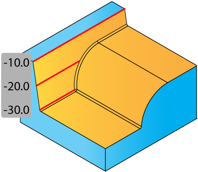
NonePasses are applied without an Adaptive Step down, and some material may be left on the top faces. |
 |
||
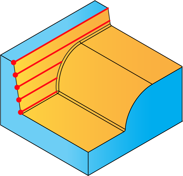
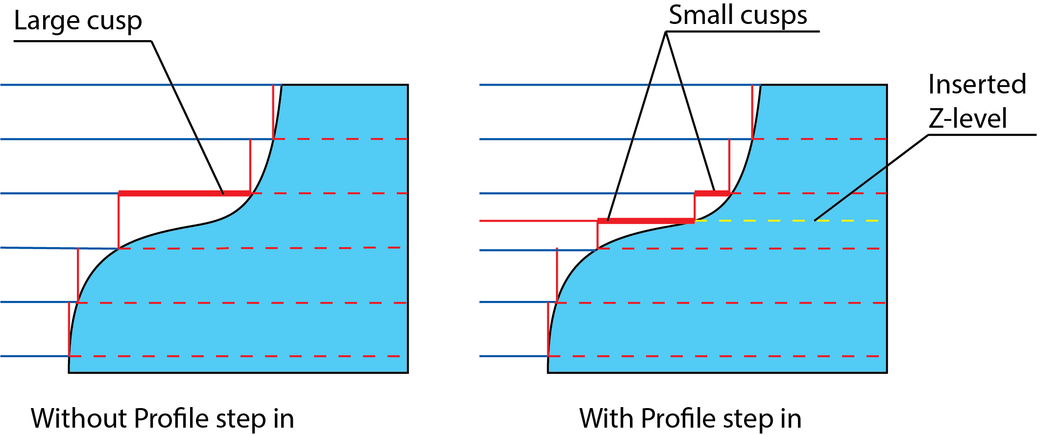
Automatically insert extra passesA pass is inserted to cut the top face; the next step down will be calculated from this pass. This parameter controls how accurately the system finds the appropriate height to insert a new slice. This parameter defines the maximal XY-distance between cutting profiles located on two successive Z-levels. When SolidCAM calculates the cutting profile at a given Z-level, the distance to the cutting profile on the previous Z-level is calculated. If the calculated value is greater than the defined Profile Step-in, SolidCAM inserts an additional Z-level and calculates the cutting profile in such a way that the distance between cutting profiles located on two successive Z-levels will be smaller than the specified Profile Step in value.
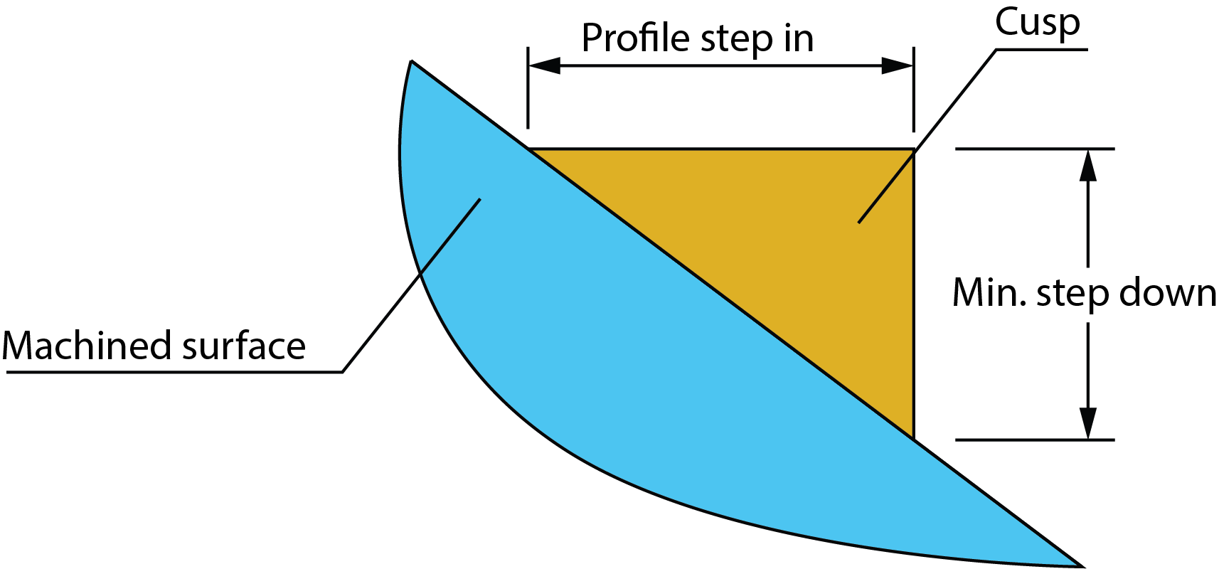
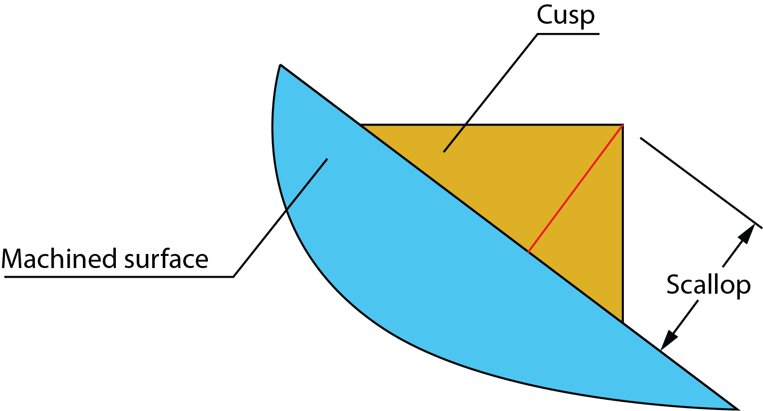
The cusp that remains after the machining can be defined either by combination of the Min. Step down and Profile step in parameters or by combination of the Min. Step down and Scallop parameters. Therefore, the Profile step in and Scallop parameters are mutually exclusive.
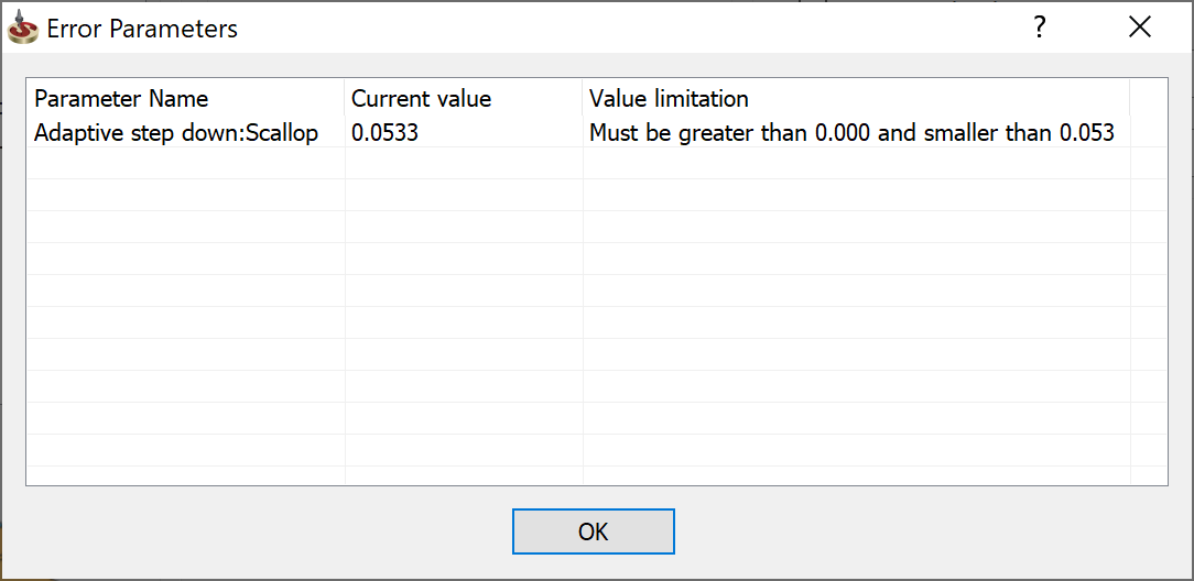
When the combination of the Scallop and Min. Step down parameters is used for the operation definition, SolidCAM performs the parameters validation according to the criteria below.
|
 |
||
User-defined Cut levelsThe cut levels can be edited manually and inserted in the User-define cut levels table. Type the Z-levels of your choice into the Z column of the table. The values will be sorted in the decreasing order. Passes are applied without Adaptive Step down, and some material may be left on the top faces. |
 |
||
Use drive curveThis option enables you to use a drive
curve to determine the heights at which passes are calculated.
Click Using this option maintains consistency while machining a curve, automatically giving a smaller step down in the shallower areas.
|
 |
Related Topics