Edit Passes parameters
If you start the machining with a formed stock instead of a rectangular or cylindrical block of material, you could trim the passes to the formed stock faces to avoid unnecessary air cutting. The tool path trimming is used either when you use a casting as stock for the part machining or you use the updated stock resulting from a number of previous operations.
For example, suppose you want to machine (using Contour roughing) the following model:
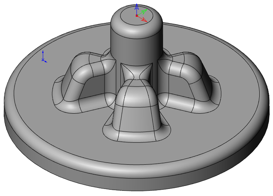
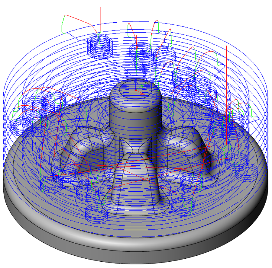
Using the Contour roughing strategy you get the following tool path.
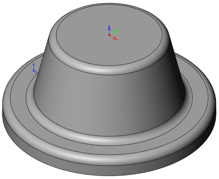
Rather than starting from a cylindrical block of material, you start with the casting shown below.
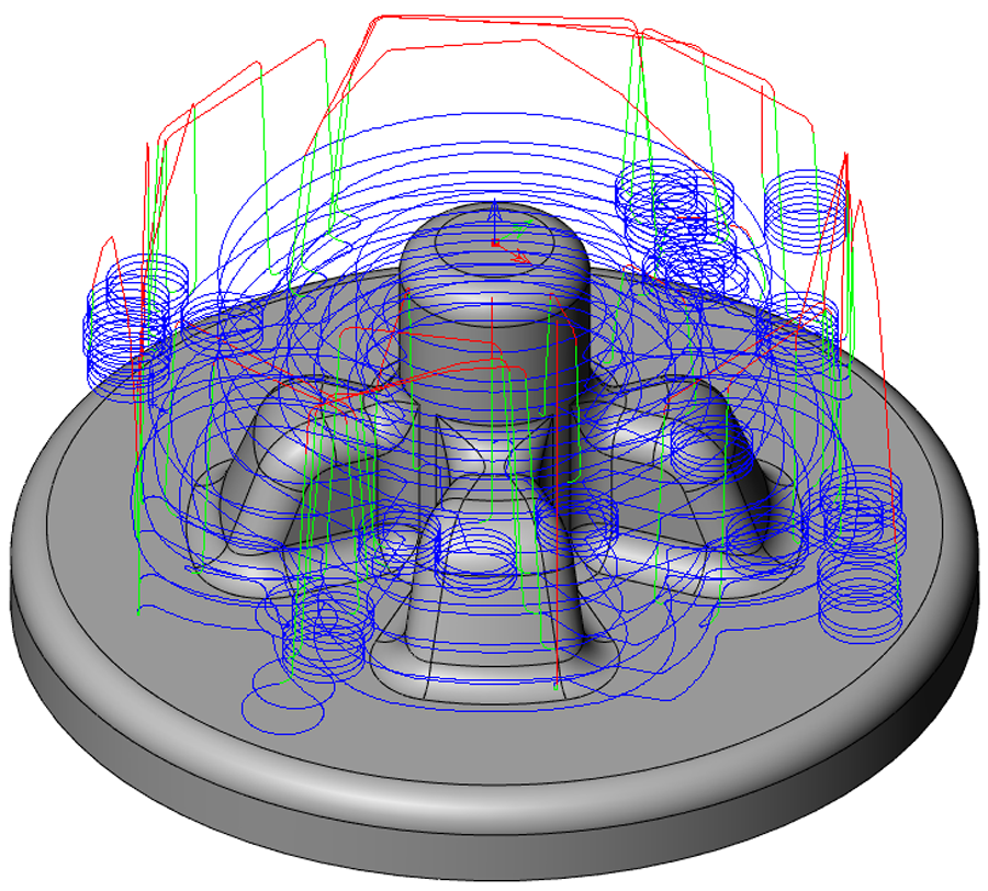
The resulting trimmed tool path is shown below.
The Edit passes page enables you to define the parameters for the trimming of passes.
Edit using surfaces
When this option is selected for Contour/Hatch roughing, SolidCAM takes the main geometry (target) as a stock and adds the specified Overthickness value.
When this option is selected for Rest roughing, SolidCAM takes the Updated Stock model as a stock and adds the specified Overthickness value.
Overthickness
This parameter defines an extra thickness that can be temporarily applied to the tool and can be set when editing passes. The use of this parameter can help to create better trimmed passes. A negative value will cause the system to select only passes that are below the model faces by the specified amount, while a positive value will select all passes that are within the specified distance from the model faces.
Axial Overthickness
Axial overthickness is an additional Vertical thickness added to the model. A negative value will cause the system only to preserve passes that are below the surfaces or stock model by the specified amount, while a positive value will select all passes that are within the specified distance from the surfaces or stock model.
Join gaps of
Passes that are in the same line and are separated by a value less than the value specified in this field will be merged to create a single pass.
Pass Extension
In this field you can define the length of Pass extension. The trimmed passes will be extended in each direction by the value specified in this field. This allows the cutter to move into the cut at Machining Feed rate instead of Rapid feed rate. This option is not available in HM Roughing strategy.
This option enables you to specify the method of machining area definition.
When the Target geometry option is chosen, SolidCAM adds the Overthickness value as an offset to the target geometry of current operation. This offset target is used as a stock.
When the Auto updated stock option is chosen, SolidCAM calculates the updated stock model after all the previous operations. The Overthickness value is added as offset to the stock, which will be used as stock for the current operation.
When the Stock by *.FCT file option is chosen, machining is performed in the area defined by an offset from the updated stock, defined in FCT file located in the CAM-Part folder. The offset is defined by the Overthickness parameter.
When the Stock by *.STL file option is chosen, machining is performed in the area defined by an offset from the updated stock, defined in STL file located in the CAM-Part folder. The offset is defined by the Overthickness parameter.
When the Reference cutter option is chosen, a user defined cutter diameter to determine the remaining stock on the part is used. The cutter type is always Ball Nose End Mill.
Show
This button displays the difference between the updated stock model and the target geometry used in the operation.
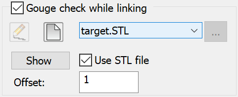
Gouge check while linking
This option enables you to automatically detect and avoid the possible collisions between the tool and the surfaces of a solid model geometry during the tool path linking only. Any geometry can be selected for the gouge checking, but this functionality is intended for consideration of your part fixtures when the tool is moving from one pass to the next.
After clicking the Gouge check while linking check box, the geometry can be defined by the following methods:
3D Model
When Use STL file is disabled (default), the geometry is defined via solid model selection.
You can choose an available geometry from
the drop-down list. The ![]() button displays
the Browse Geometries dialog box that enables you to visualize the geometry
during the selection process; the selected geometry is highlighted in
the SOLIDWORKS Graphics Area.
button displays
the Browse Geometries dialog box that enables you to visualize the geometry
during the selection process; the selected geometry is highlighted in
the SOLIDWORKS Graphics Area.
The ![]() button
displays the 3D Geometry dialog box that enables you to define a new geometry.
button
displays the 3D Geometry dialog box that enables you to define a new geometry.
The ![]() button
enables you to edit an existing geometry.
button
enables you to edit an existing geometry.
STL
When Use STL file is enabled, the geometry is defined using a STL file that exists on your computer.
You can choose an available STL file from the drop-down list; files located in the CAM-Part folder will appear in the list.
The ![]() button
displays the Choose STL dialog box that enables you to define a new STL
file from any location on your computer.
button
displays the Choose STL dialog box that enables you to define a new STL
file from any location on your computer.
Show displays in the SOLIDWORKS Graphics Area the chosen geometry (either 3D Model or STL) for which its surfaces will be protected during the tool path linking only.
Offset - This option enables you to set an offset value for the clamps that holds the workpiece while machining.
Stock definition in Rest Roughing
In the Rest roughing operation, you can control the number of recalculations and save time.
You can choose how the stock for the operation is defined: either By selected operations or Automatically.
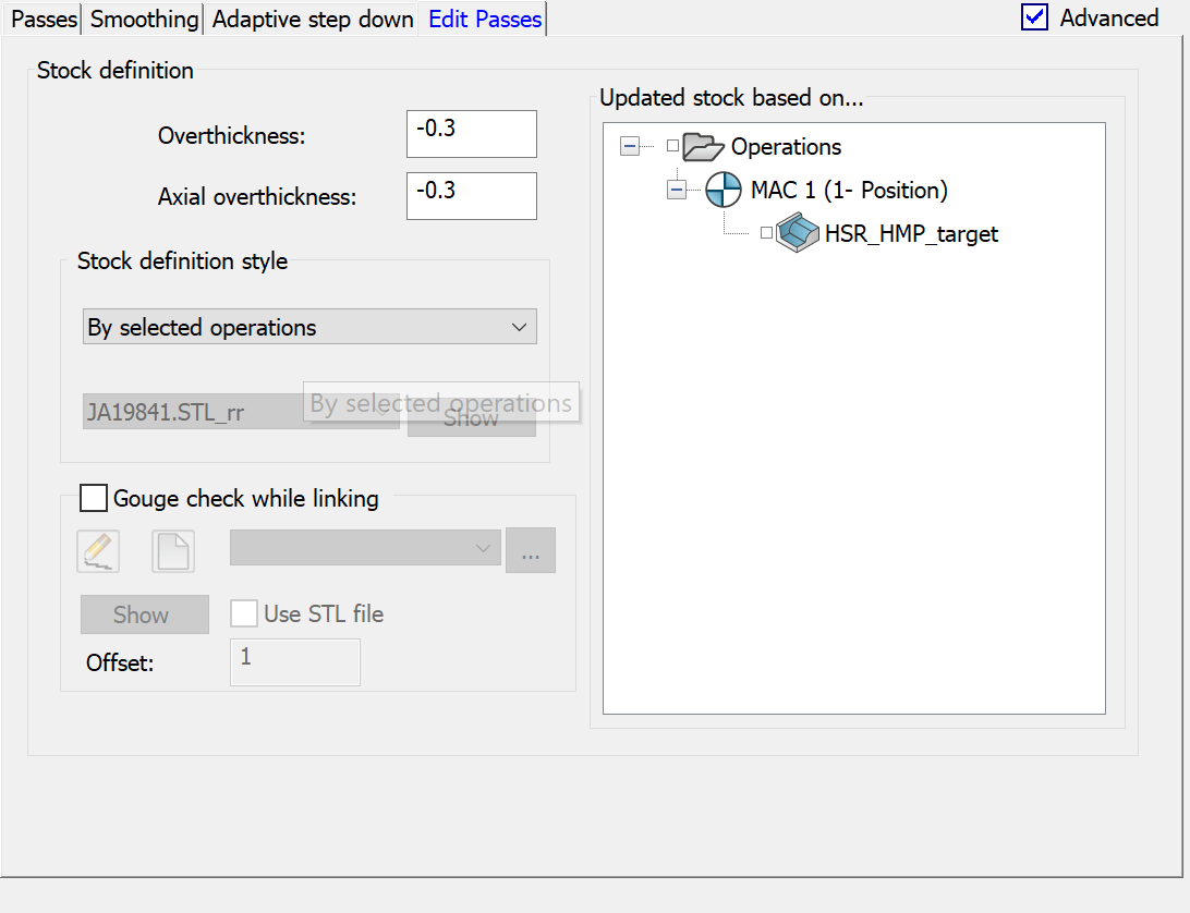
When you choose the Automatically option from the list, the updated stock is obtained after processing all previous operations.
When you choose the By selected operations option, you can see all operations preceding the current operation in a fragment of the CAM-tree. Any previous operation, whether calculated or not, can be selected for updated stock definition. Select the operations by clicking the check box near the operation name. You can also select all operations by clicking the check box near the Operations header.
Related Topics