Sorting
The Sorting tab enables you to define the order and direction of the cuts.
Cutting method
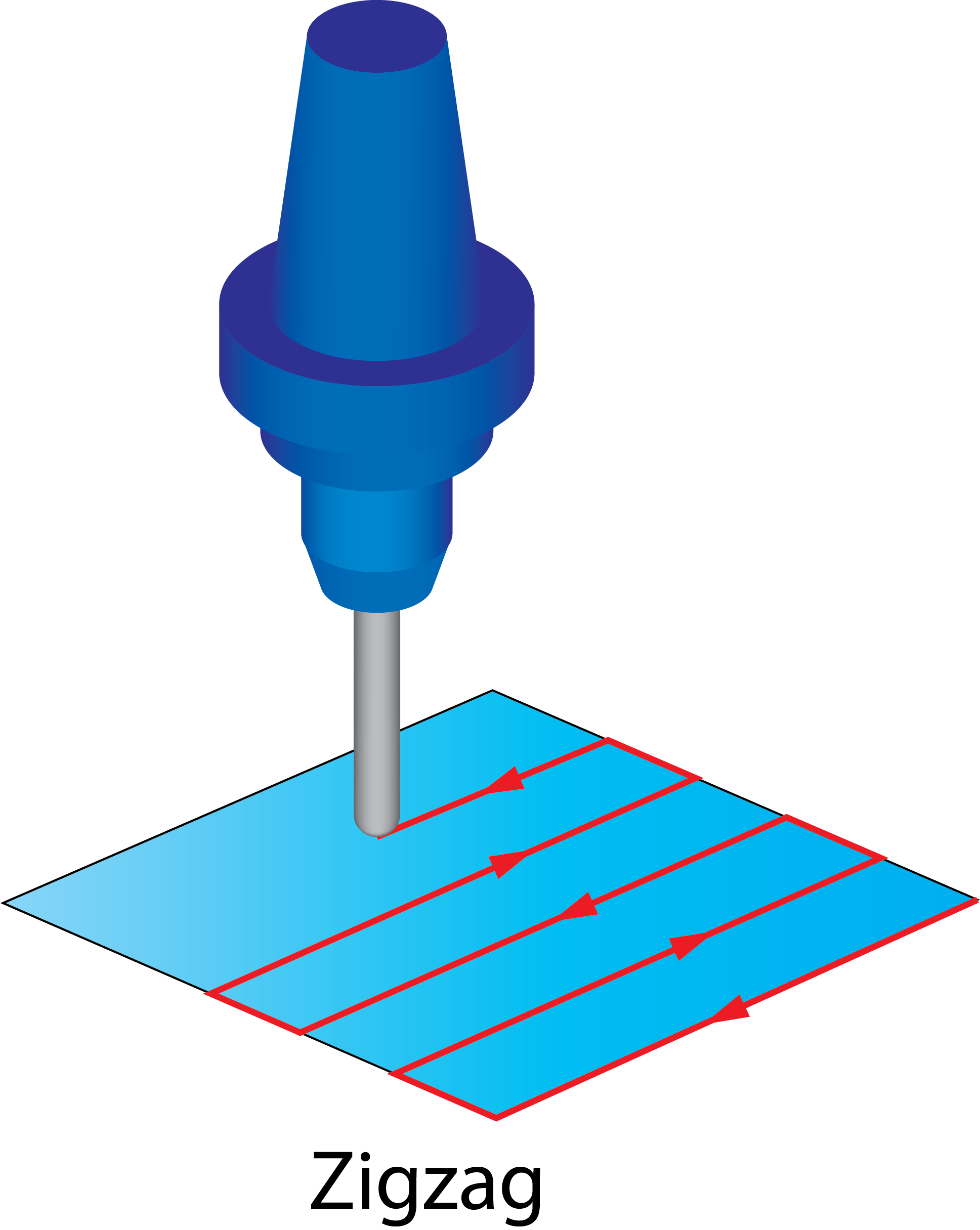
This option enables you to define how the cuts are connected. It has three choices: Zigzag, One Way, and Spiral.
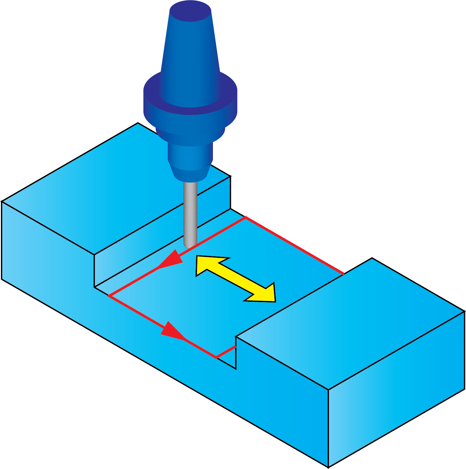
ZigzagWhen the Zigzag option is chosen, the machining direction changes from cut to cut. The tool performs the machining of a cut in the specified direction, then moves to the next cut and machines it in the opposite direction. |
 |
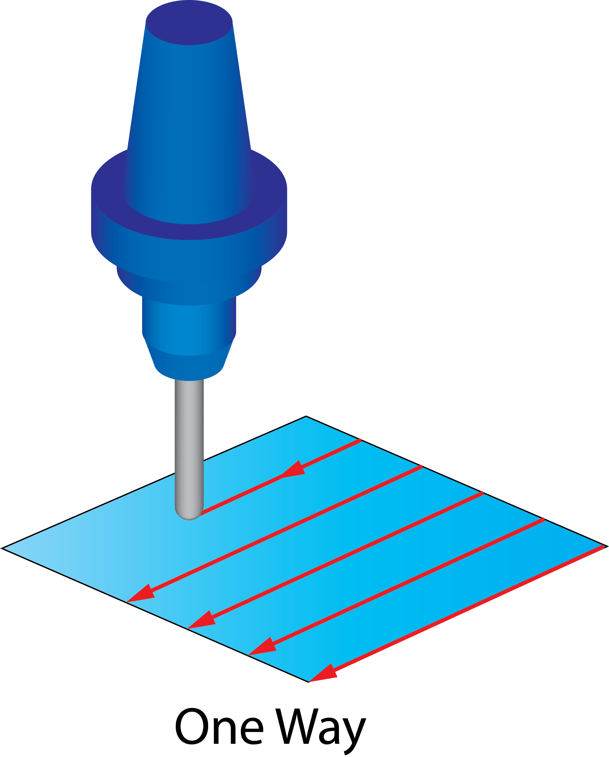
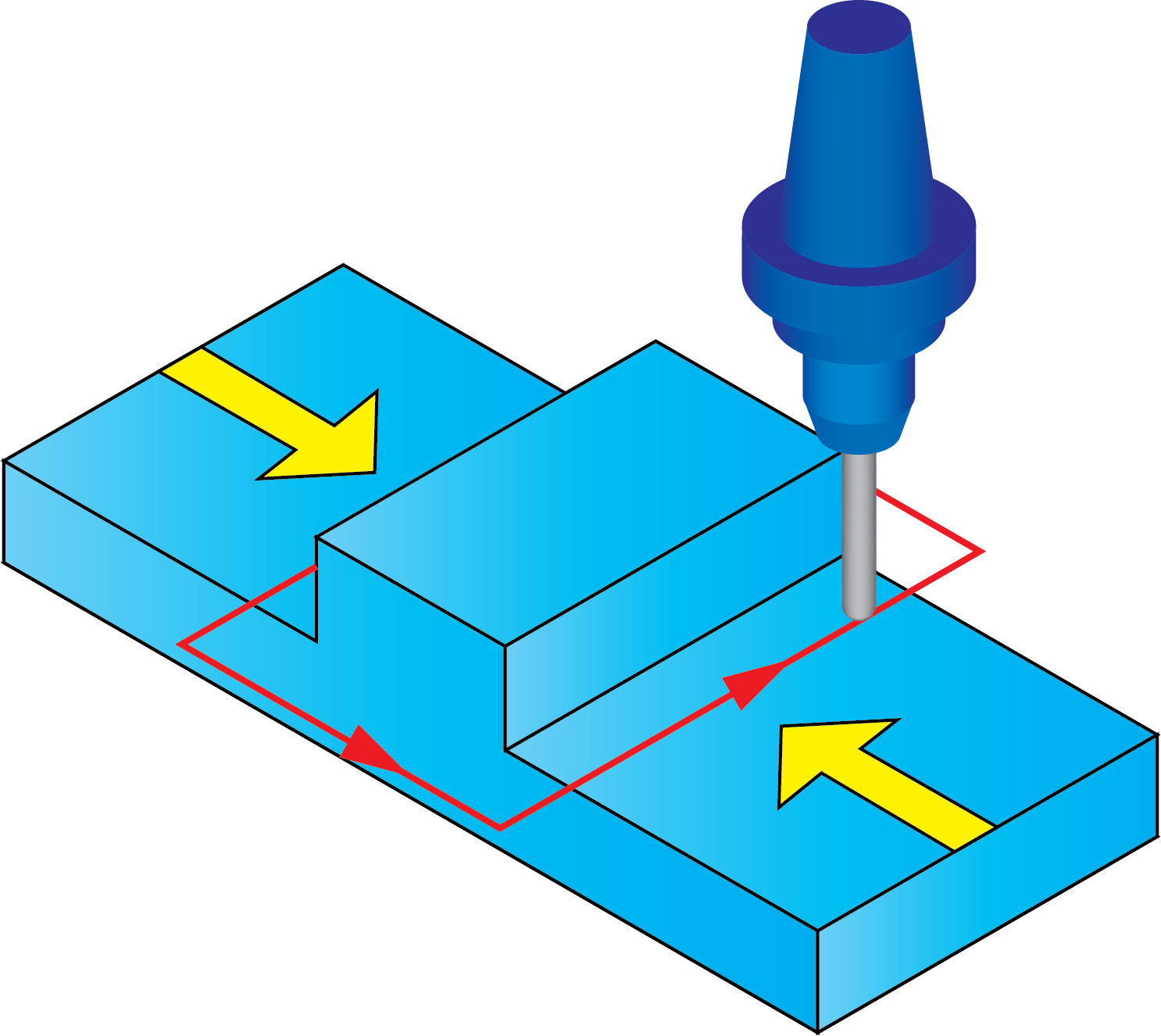
One WayWhen the One Way option is chosen, all cuts are machined in the same direction. The tool performs the machining of a cut in the specified direction, then moves to the start of the next cut and machines it in the same direction. |
 |
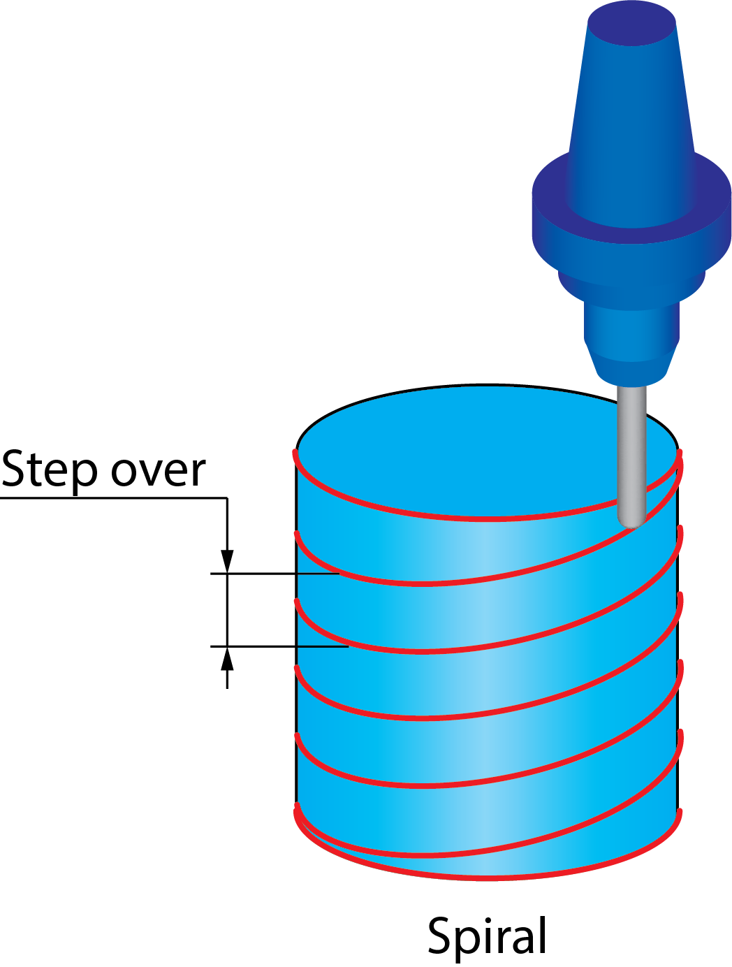
SpiralWith the Spiral option, SolidCAM generates a spiral tool path around the drive surface according to the chosen pattern. The spiral pitch is defined by the Max. step over parameter. |
 |
|
This cutting method is available for use with all the strategies except for the Projection strategy. |
Clicking Advanced displays the Advanced options for spiral machining dialog box.
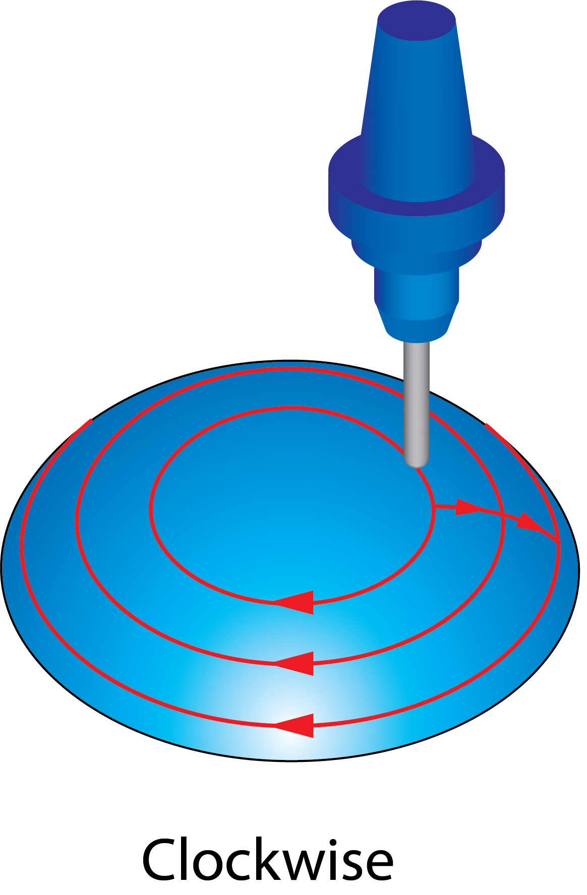
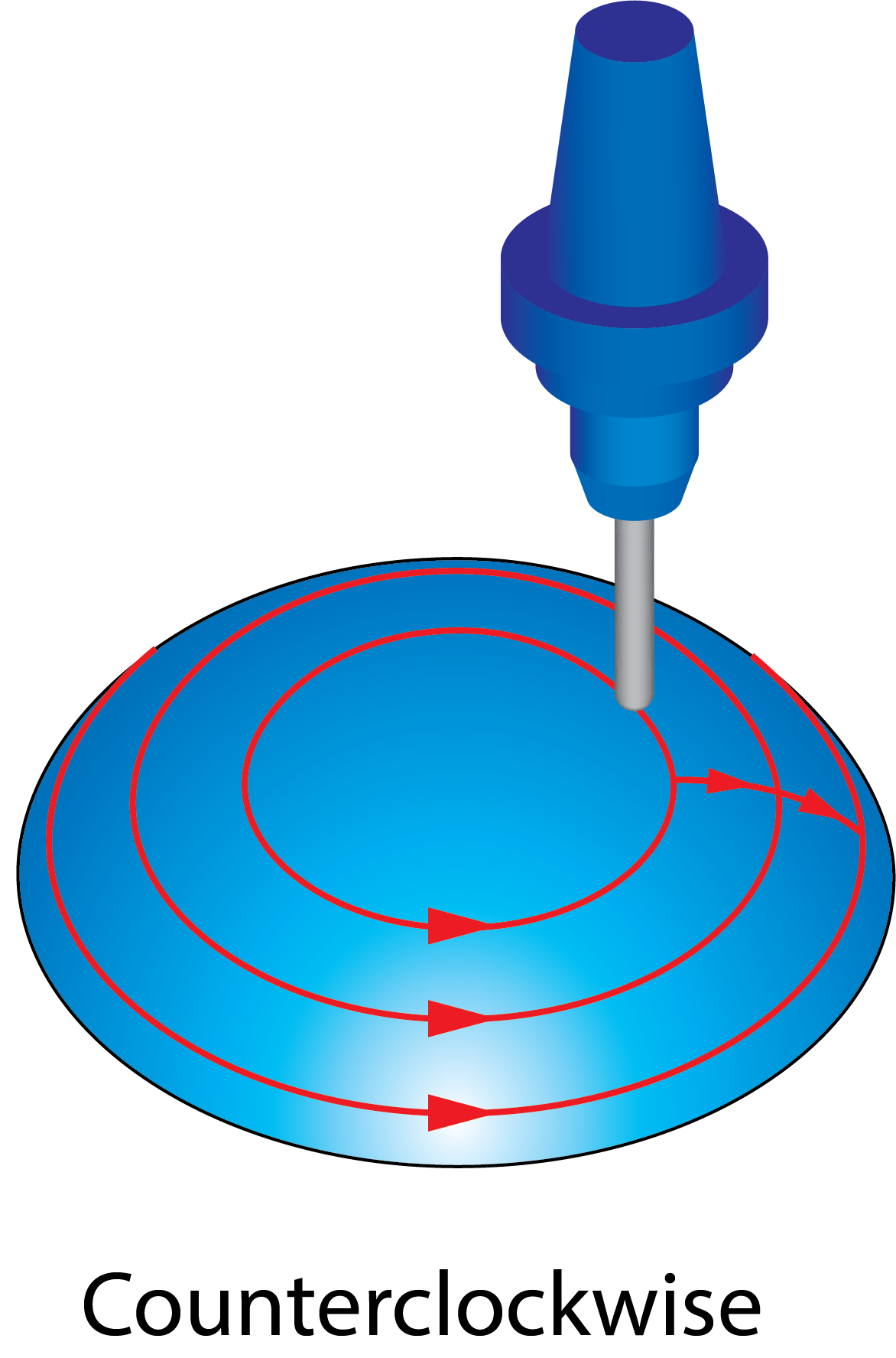
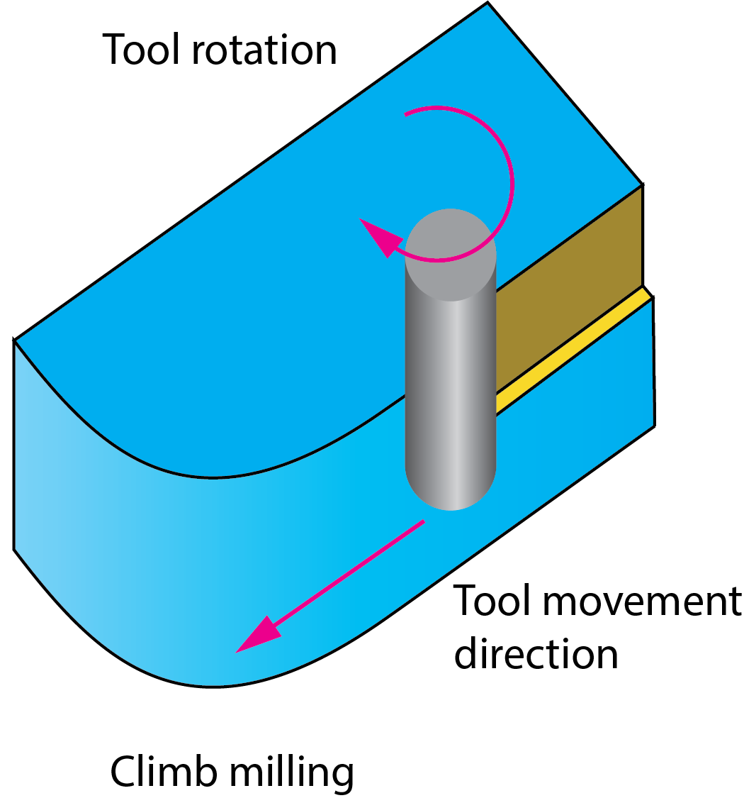
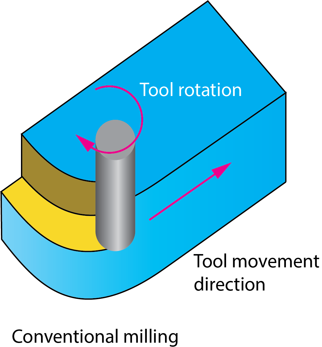
Direction of machining
When the One Way or Spiral options are chosen for Cutting method, SolidCAM enables you to define the following directions of cuts:
 |
|
 |
|
|
 |
|
 |
Cut order
The Cut order option enables you to define the sequence of the cuts. The following options are available:
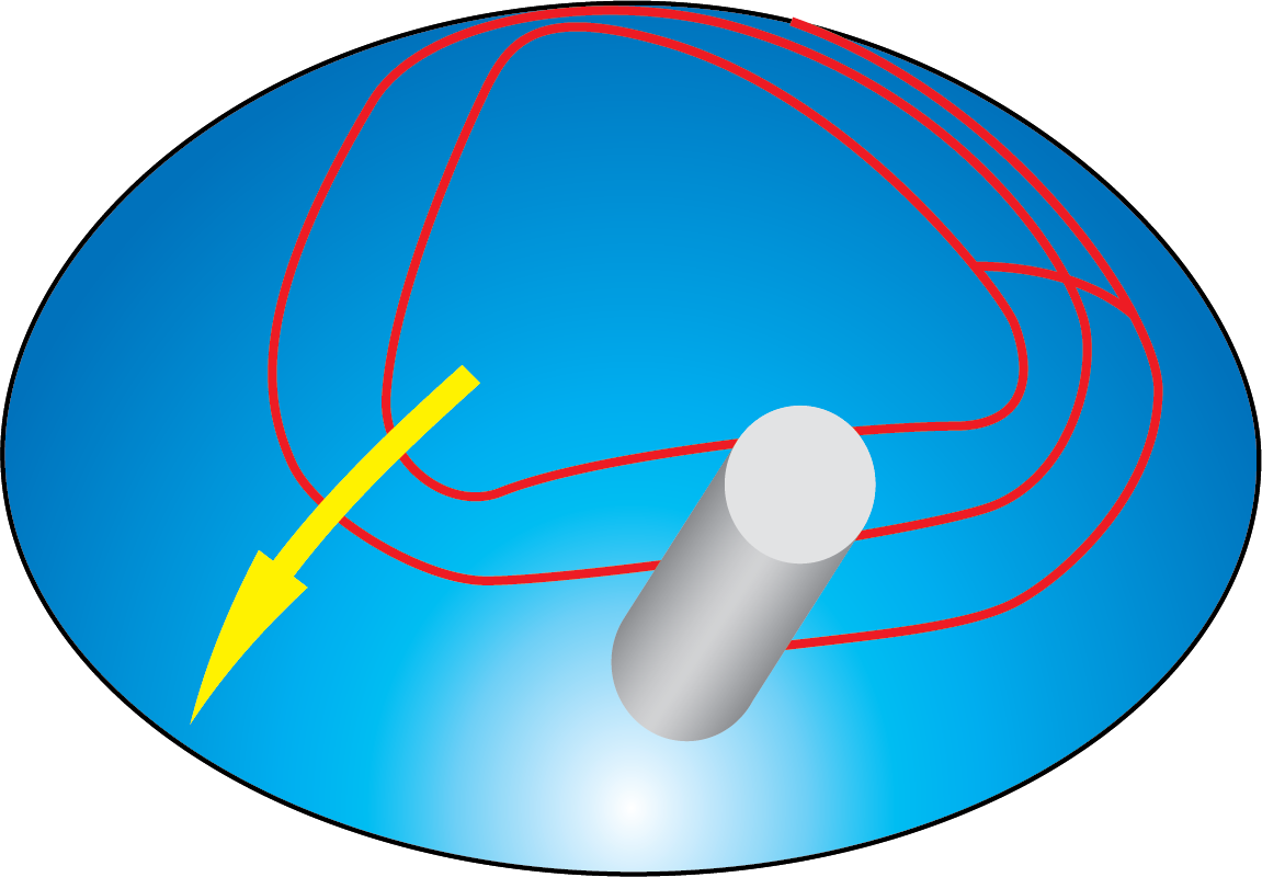
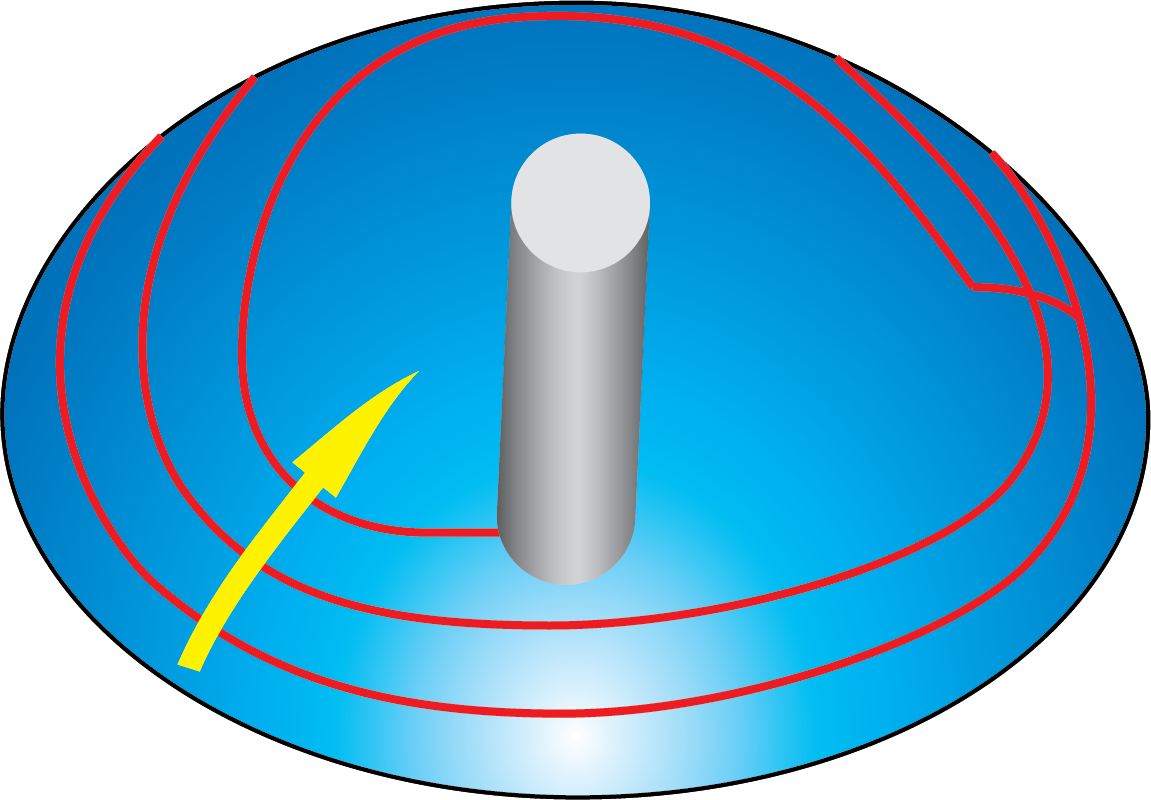
Machine by
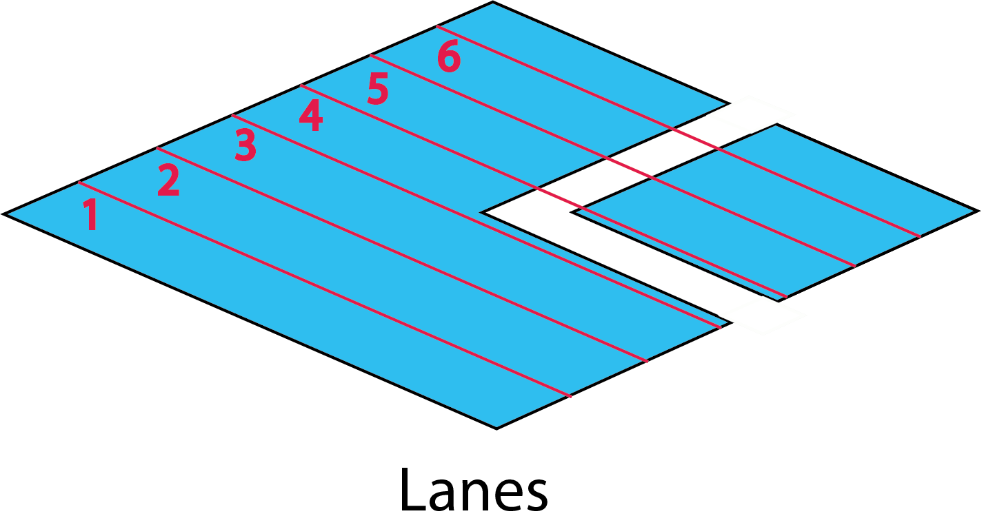
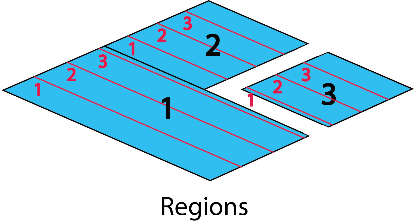
SolidCAM enables you to define the machining order for a Sim. 5-axis operation. The Machine by list enables you to choose the order of machining of certain areas; it defines whether the surface will be machined by Lanes or by Regions. The generated tool path usually has a topology of multiple contours (lanes) on the drive surfaces. When the tool path is generated in many zones, it might be preferable to machine all the regions independently. |
 |
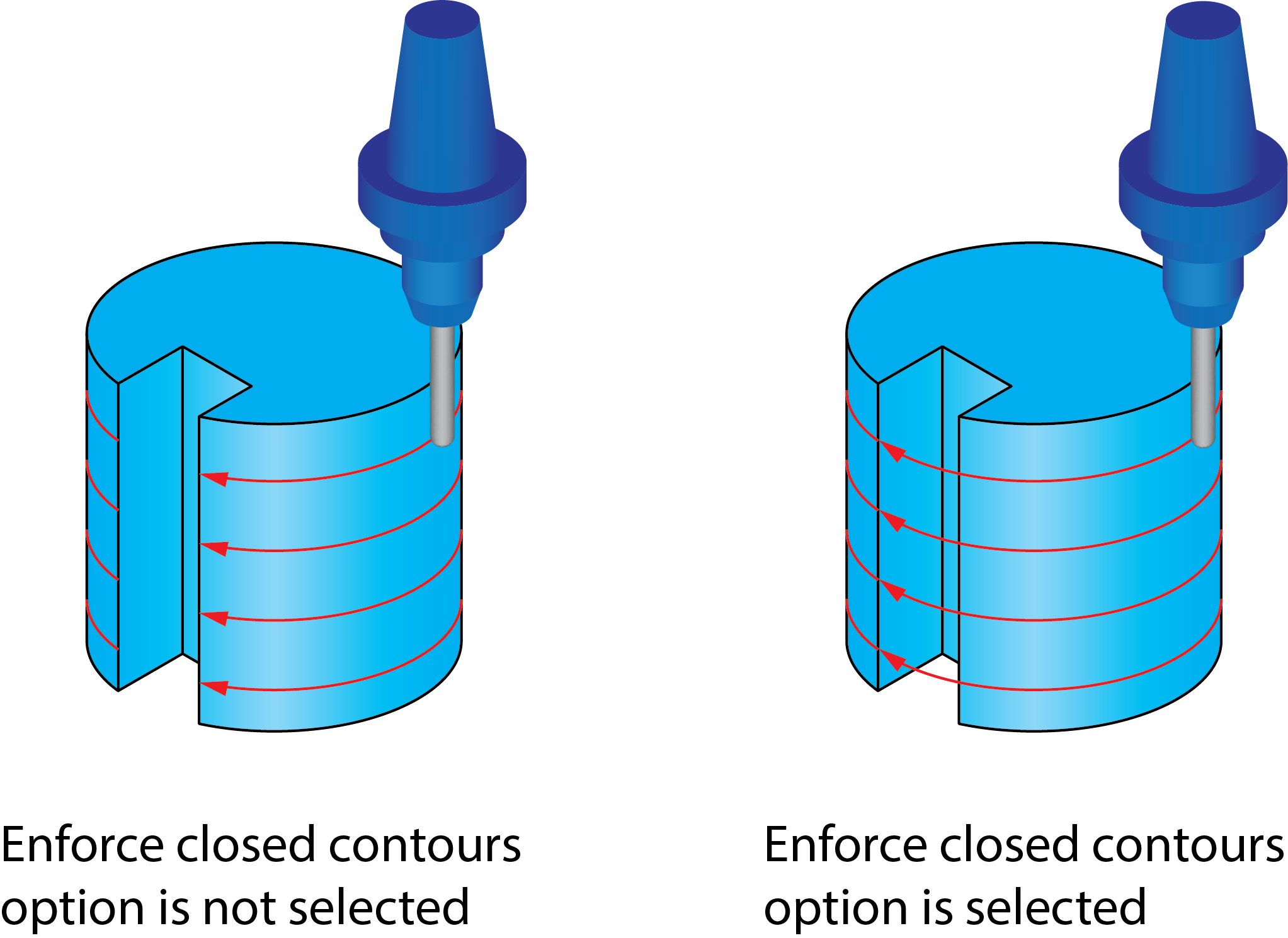
Enforce closed contours
When the geometry is not completely closed, the Enforce closed contours option enables you to close the geometry and perform the machining of closed contours. |
 |
|
This option is available only with the CW and CCW options chosen for Direction of machining. |
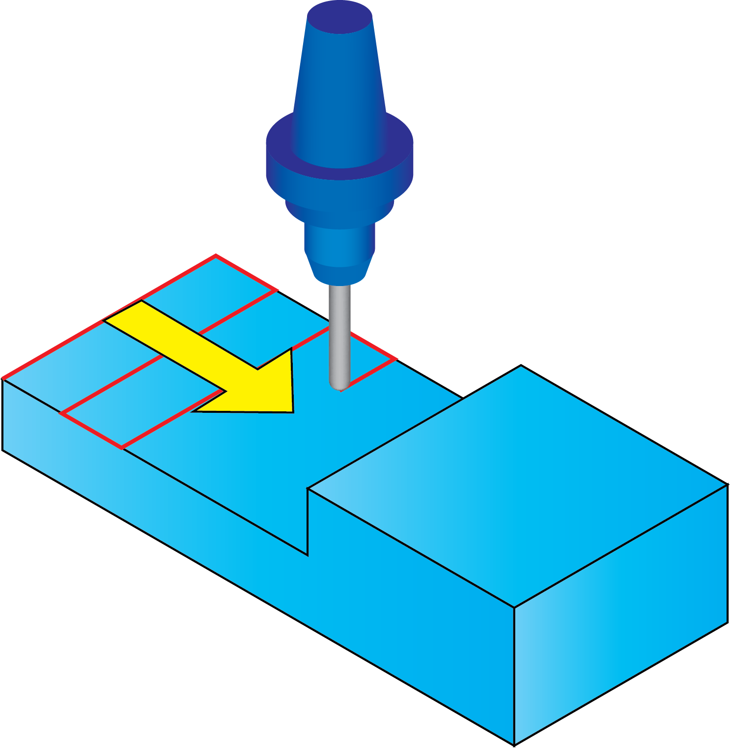
Flip step over
When the Standard option is chosen for the Cut order, the Flip step over parameter enables you to change the direction of the cuts. In the image, the machining initially starts from the top of the model. |
 |
With the Flip step over option, the machining is reversed and starts from the edge. |
 |
Start point
Clicking the Start point button displays the Start Point Parameters dialog box.
Reverse
The Reverse parameter changes the start point of the tool. When the Reverse check box is selected, the tool starts from outside and moves towards the center. If this check box is not selected, the tool moves from inside towards outside
|
This parameter is available only in the Projection (Radial) strategy. |
Cutting side
This section enables you to position the tool at the Center, Left or Right side of the tool path.
|
This option is available only in Projection (User-defined and Offset) strategies. |