Surface quality
The Surface quality tab enables you to define the parameters that affect the surface finish quality.
Cut tolerance
The Cut tolerance parameter defines the tool path accuracy. The Cut tolerance parameter defines the chordal deviation between the machining surface and the tool path; the tool path can deviate from the surface in the range defined by the Cut tolerance.
You can type the value manually or adjust it using the slider.
A smaller Cut tolerance value gives you more tool path points on the drive surface resulting in more accurately generated tool path. The result is a better surface quality, but the calculation time is increased. |
 |
A greater Cut tolerance value generates less points on the tool path. After the machining, the surface finish quality is lower but the calculation is much faster. |
 |
Distance
The Cut tolerance parameter defines the number of tool path points on a surface. The distance between these points is not constant and depends on the surface curvature: there are less points calculated on flat surfaces and more points on curved surfaces.
The Distance parameter enables you to define the maximal distance between two consecutive tool path points. In other words, when the Distance option is used and the value is defined, SolidCAM generates tool path points at least at every specified distance. |
 |
When the Distance option is not used, the number of tool path positions is determined by the Cut tolerance parameter. |
 |
Step over
Maximum step over- This parameter defines the maximum distance between two consecutive cuts. The definition of the Maximum step over parameter is different for each machining strategy: |
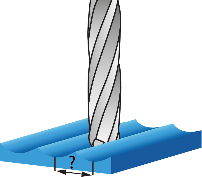 |
For the Parallel cuts strategies, the Maximum step over parameter defines the distance between the parallel planes.
For the Parallel to curve/surface technology, the Maximum step over defines the distance between two consecutive passes along the drive surface.
For the Perpendicular to curve technology, the Maximum step over is measured along the curve, perpendicular to which the cutting planes are created.
For the Morph between two curves/surfaces technology, the Maximum step over defines the distance between two consecutive passes along the drive surface.
For the User-defined strategy of the Projection technology, the Maximum step over parameter is not relevant, because the projection curves can be chosen arbitrarily. For the Spiral and Radial strategies, the Maximum step over defines the distance between two consecutive passes.
When the Parallel to curves or Morph between two boundary curves is selected as Technology, The Step over calculation method enables you to calculate the step over evenly over multiple surfaces and provides a good pattern of tool path. From the list you can choose between the options of Approximate and Exact.
Extend edge curve- When this check box is selected, it gives better control over tool path results. The advantage is that you can get different tool paths without adding additional geometry to the edge curves.
|
This option is available in the Technologies of Parallel to curves or Morph between two boundary curves only when the Step over calculation method is selected as Approximate. |
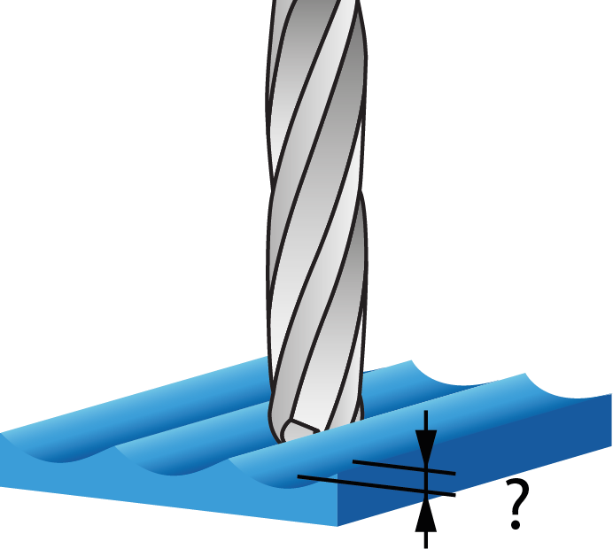
Scallop
The Scallop parameter enables you to define the cusp height of the machined surface. The Scallop parameter corresponds to the Maximum step over parameter. When the Scallop is defined, SolidCAM automatically updates the Maximum step over value according to the chosen tool diameter and the Scallop; vise versa, when the Maximum step over is redefined, SolidCAM automatically recalculates the Scallop value. When the Parallel to curves or Morph between two boundary curves is selected as Technology, The Step over calculation list enables you to calculate the step over evenly over multiple surfaces and provides a good pattern of tool path. From the list you can choose between the options of Approximate and Exact. |
 |
|
The Scallop parameter is available only when a Ball Nose Mill tool is chosen for the operation. |
Advanced options for surface quality
The Chaining tolerance parameter defines the tolerance of the initial grid used for the tool path calculation. The recommended value is 1 to 10 times the Cut tolerance. In some cases, for simple untrimmed surfaces, the Chaining tolerance value can be defined up to 100 times the Cut tolerance and would increase the calculation speed significantly.
The surface contact paths are created while analyzing and slicing the surface patches. If due to slicing the tool path topology becomes very complex (for example, patches parallel to curve and surface are very large), sometimes the surface contact paths cannot be constructed safely.
If the Automatic chaining tolerance check box is selected, a finer grid (based on the Max. Step over value) is applied for initial analysis of surface patches, thus delivering slow but safe results for surface contact points.
Synchronize points
The Synchronize points option enables you to equalize the spacing and number of points on all contours.
|
This option is enabled only when the Distance option is selected. |
Adaptive cuts
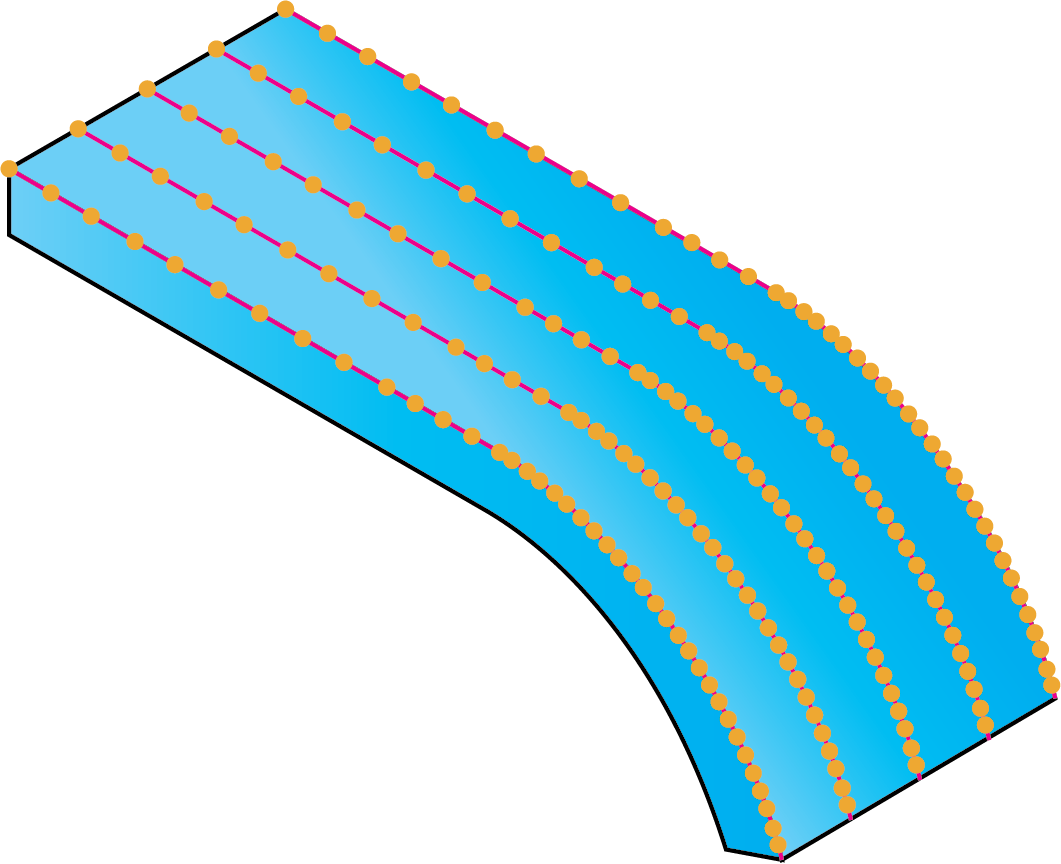
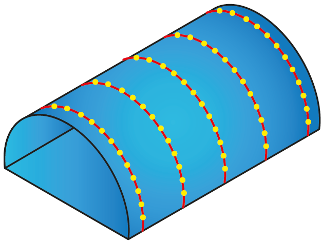
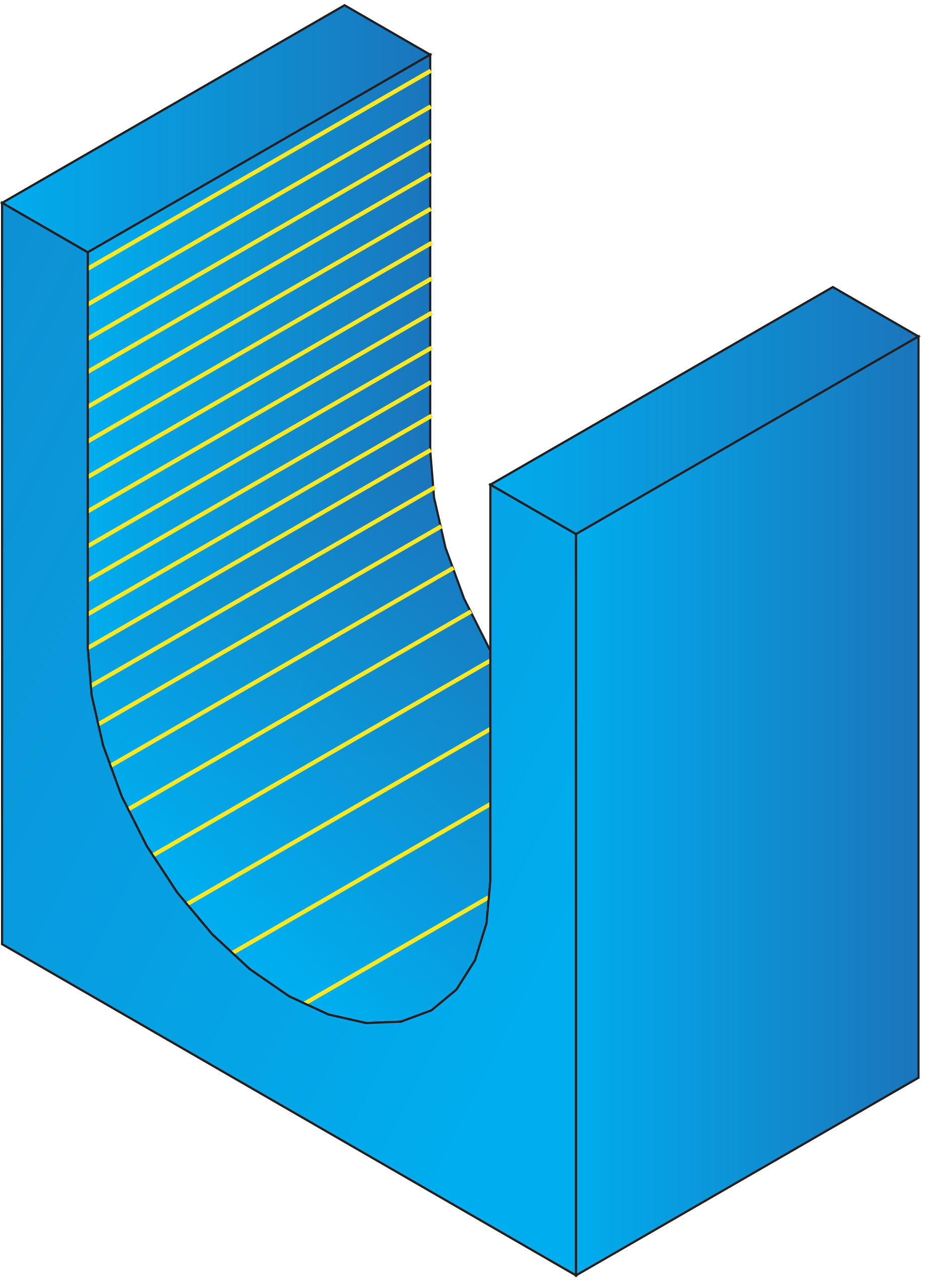
This check box enables you to adjust the step over between tool path passes in an adaptive way, in order to ensure an acceptable distance between adjacent passes. This option is especially useful in machining of steep surfaces, molds, and U-shaped parts.
When this check box is not selected, the tool path passes can be distributed in such a manner that the distance between them is varying throughout the tool path. In certain cases, such distribution of passes may result in poor quality of surface machining. |
 |
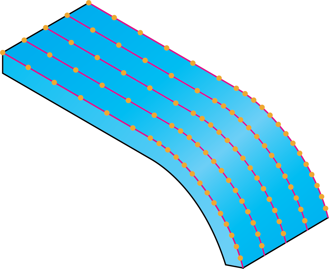
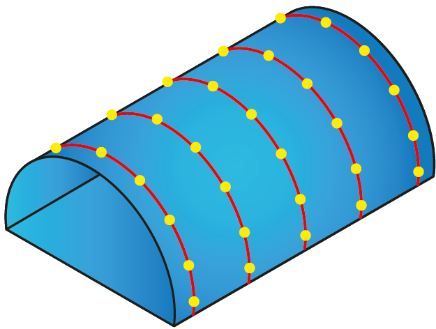
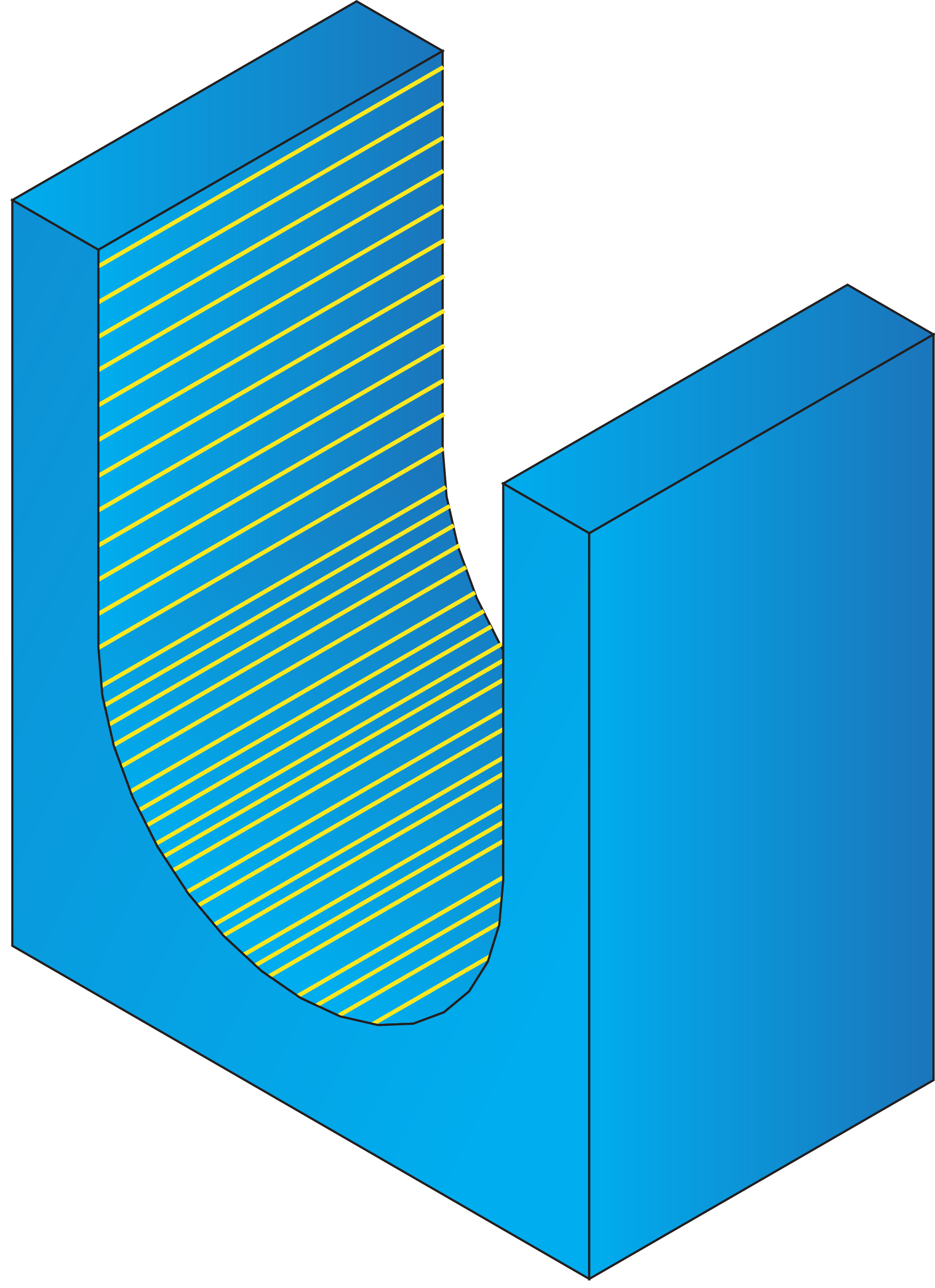
When this check box is selected, additional lines can be inserted in the tool path if the distance between two adjacent passes is considered too large. As a result, the number of calculated cuts increases. |
 |
|
This option is not available for use with the Parallel cuts, Perpendicular to curve and Projection strategies. Pay attention that when this option is used, the calculation time increases. |