Feature Recognition Mode
The Feature Recognition Modes of iMachining 2D can detect and define the machinable features of your parts based on your selections in combination with the solid model data.
|
iMachining's Feature Recognition technology analyzes the Stock and Target models. Therefore, it is important they are accurately defined in the CAM-Part Definition. |
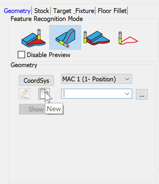
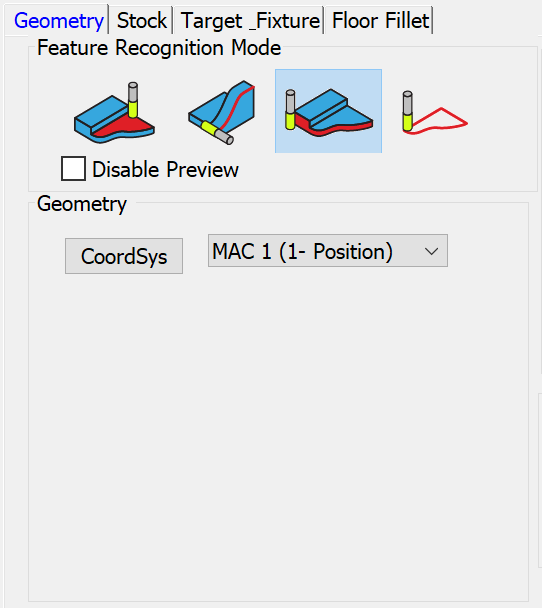
The Geometry definition process is started by first selecting one of the following modes:
![]() Chains without
Feature Recognition
Chains without
Feature Recognition
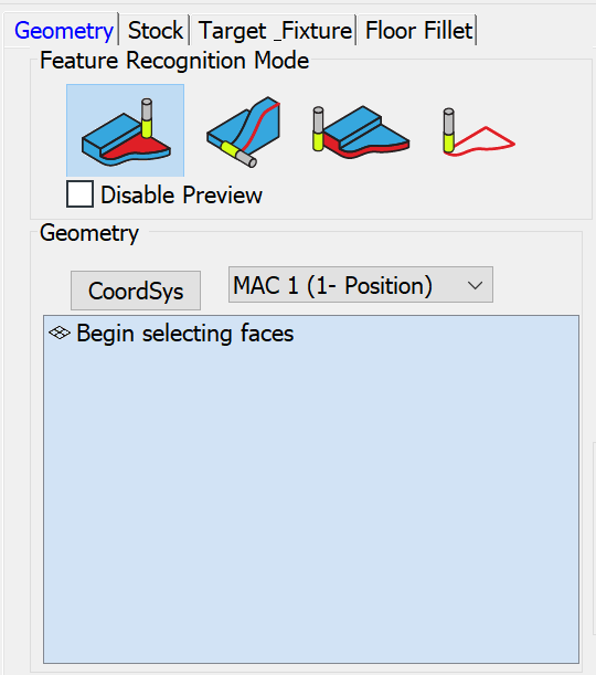
Feature Recognition by Faces
When using this mode, the Geometry section displays the Faces Selection box. Upon clicking it, you are prompted to Begin selecting faces.
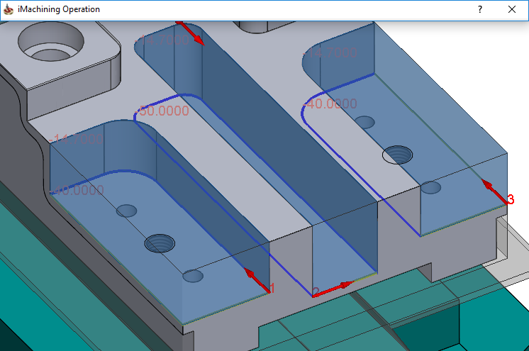
With the Faces Selection box activated, simply click on the floor faces of the pocket features that you want machined by the operation. The faces can be at different depths.
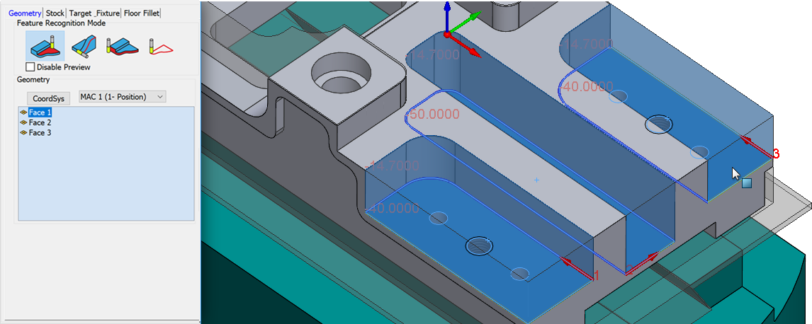
In the example above, three faces are selected. Upon picking each face, it appears in the Faces list and two major processes are performed:
- The Smart Face feature builds and defines the chain geometries.
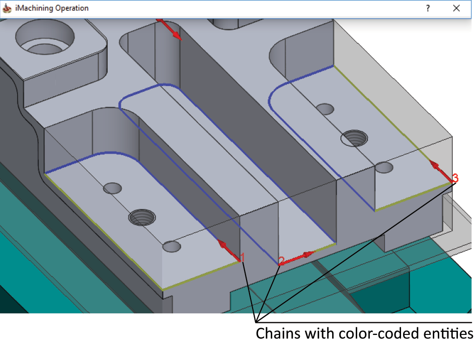
The chains are displayed in the SOLIDWORKS Graphics Area. Walls and open edges are identified and marked accordingly. The hole features are detected but ignored.
- According to the Updated Stock model (USM) and the selected faces of the Target model, iMachining automatically detects and defines the corresponding pocket features and their levels. Highlighted and displayed in the SOLIDWORKS Graphics Area are the generated iMachining regions, which are a visual representation of the material that will be removed by the operation.
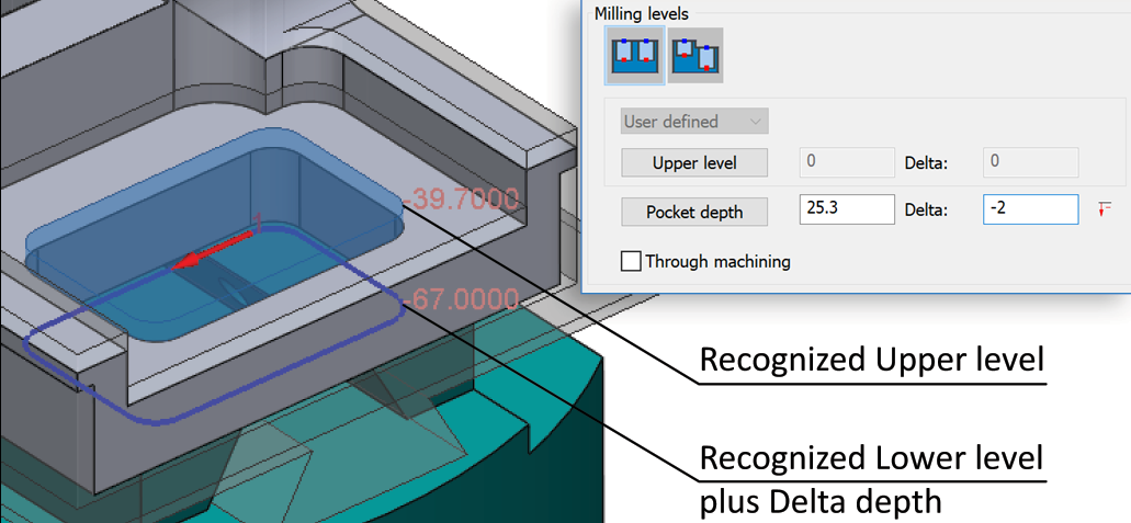
Also displayed for each iMachining region are both the Upper level and Lower level values.
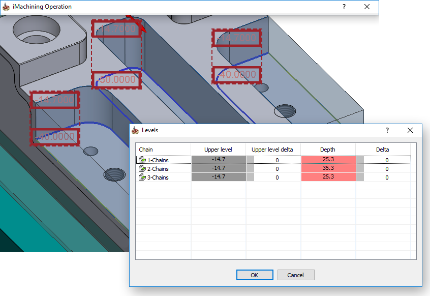
The associated data is automatically written to the Milling levels of the operation. Since the pockets have varying depths in this case, their Upper level and calculated Depth values can be seen in the Variable Levels dialog box.
With just a single click, you can define for each pocket feature both the machining geometry and levels. Apart from the Tool definition, this fulfills the minimum requirements for defining an iMachining operation.
Feature Recognition by Chains
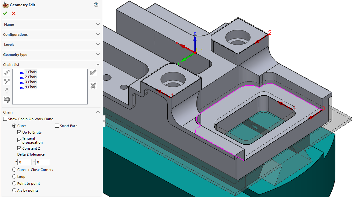
When using this mode, the Geometry section displays the familiar options relevant to SolidCAM's standard chaining method.
You can use the appropriate options to define new, edit existing or select from/browse for predefined chain geometries.
The geometry, which can consist of closed and/or open chains, is best suited for features that cannot be defined via floor face selection. Such features can include through pockets and side profiles.
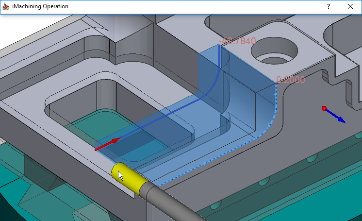
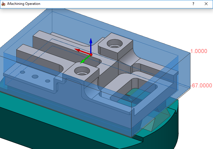
Example 1: Through pockets milling
In the example below, the geometry chain is defined by selecting the lower contour of the through pocket feature.
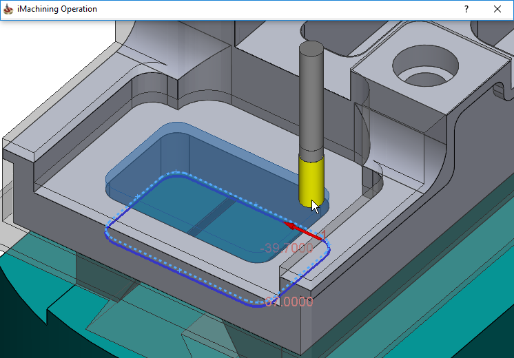
According to the chain definition and the USM, the exact area that requires machining is detected automatically.
In this case, the Upper level is extended in the positive Z-direction to the adjusted depth of the previously machined semi-open pocket.
The Pocket depth is defined according to the chain selection depth. For this operation, a Delta depth is specified so the tool can perform the machining deeper than the part bottom edge.
|
When specifying a Delta depth, the chain geometry is projected to the adjusted depth. |
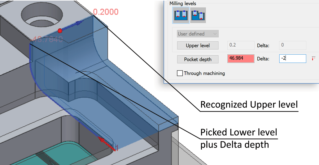
Example 2: Side milling of profiles
In the example below, using a different Coordinate System Position, the geometry chain is defined by selecting, along the side of the part, the contour of a profile feature.
According to the chain definition, USM and one simple modification, the area that requires machining is defined.
In this case, the Upper level is extended in the positive Z-direction to the roughing offset that remains on the adjacent side wall after the outside shape machining.
The Pocket depth is defined by selecting an appropriate point on the Target model plus specifying a Delta depth.
This mode, although requiring one or two user inputs, can significantly reduce your programming time in addition to the savings already provided by iMachining 2D operations. While it is true in the two examples shown, it's especially true in cases of complex geometries that would otherwise require custom sketching in SOLIDWORKS.
Outside Feature Recognition
When using this mode, other than the Coordinate System selection, the Geometry section is intentionally left blank because no other user inputs are required for the Geometry definition.
The only requirement is to click the corresponding button when you want to machine the entire outside shape of your part.
After analyzing the solid model data, iMachining automatically detects and defines the machinable surrounding stock and its levels.
As shown in this example, the Upper level is defined according to the top of the Stock model and the Pocket depth is defined according to the bottom of the Target model. The displayed Lower level value includes a negative Delta depth measurement.
Chains without Feature Recognition
When using this mode, the Geometry section displays the familiar options relevant to SolidCAM's standard chaining method.
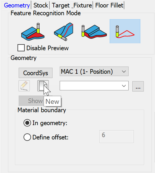
Also displayed in the Geometry section is the Material boundary feature, which is not available for use with any of the other modes.
By default, this mode enables you to define your machining geometry exactly as you did prior to SolidCAM 2019 and without the capabilities of iMachining's Feature Recognition technology.