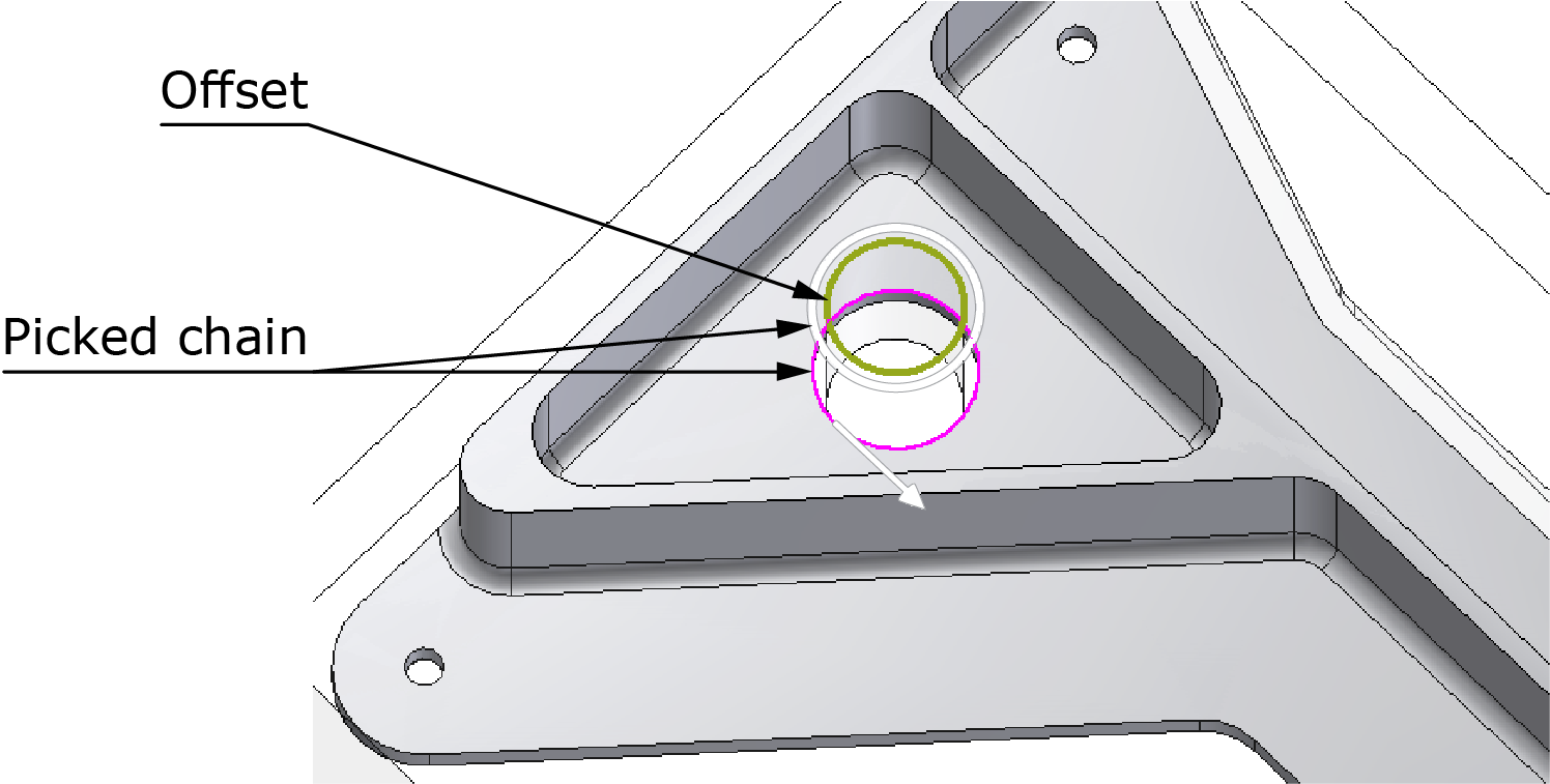
Material boundary
In iMachining 2D, this section is enabled when Chains without Feature Recognition is selected. This method of Geometry definition enables you to automatically generate geometry chains by defining an offset. The offset is generated to one side of an existing closed or open geometry chain.
|
In some cases, by eliminating the need to sketch a working area in SOLIDWORKS, this method of generating geometry chains can help reduce programming time. |
The Material boundary feature is only suitable for certain circumstances, where the starting stock is marginally larger than the target and the initial shape is the same as the final shape. Provided that the size and shape meet these requirements, a Material boundary can be used to define the following iMachining 2D geometries:
|
When selecting chains, it is important that the offset is generated to the left side of the chain direction; therefore, when using this method of Geometry definition, chains must always be picked to indicate climb cutting. |
Closed pocket with entry geometry
Any shape can be used for entry geometry, but it must be the same as the final shape. In this example, a hole that is considered a precut area is used for entry.
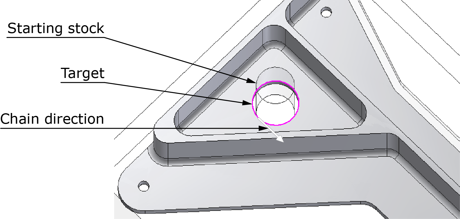
To define this type of geometry using the Material boundary feature, the working order is as follows:
- To start the Geometry definition, click
 on the Geometry page of the iMachining Operation dialog box.
 - Pick the chain entities that define the pocket contour. When
closed, the selected chain is displayed in the Chain List of the
Geometry Edit dialog box. To ensure the entry chain is generated
on the inside of the selected closed chain, the chain direction
must indicate climb cutting. Click
 to confirm the chain
selection and exit the Geometry Edit dialog box.
to confirm the chain
selection and exit the Geometry Edit dialog box. - In the Material boundary section, choose the Define offset option and enter the appropriate offset value. To accurately define the offset, you have to consider the size of the tool in addition to the starting stock.
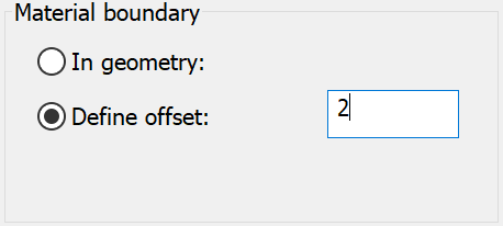
As defined by the offset value, the iMachining technology automatically generates the internal entry chain to complete the Geometry definition. Show Geometry on operation editing in the SolidCAM Settings enables you to preview the auto-generated geometry chain.
The geometry chain projected in white represents the picked chain, while the one projected in green represents the auto-generated chain.
Open pocket with island
A boss feature already machined and then later reduced in size is a typical example of this type of geometry. The working order is similar to the above with only one difference. The chain on island contour is selected; and as defined by the offset value, the iMachining technology automatically generates the external chain to complete the Geometry definition.
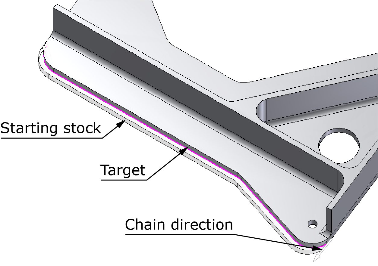
Semi-open pocket
In this example, the outer shape was modified from the original specifications with only a marginal reduction of one side.
To define this type of geometry using the Material boundary feature, the working order is as follows:
- To start the Geometry definition, click the
button on the Geometry page of the iMachining Operation dialog
box.
- Pick the chain entities that define the semi-open pocket contour.
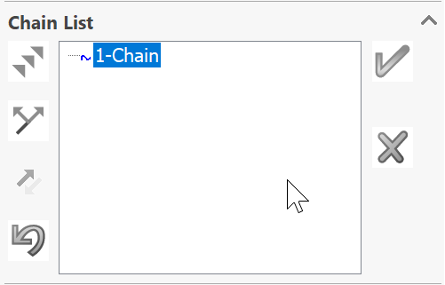
In the Chain List section of the Geometry Edit dialog
box, click the
 button to define the chain as open.
The selected chain is displayed in the Chain List.
button to define the chain as open.
The selected chain is displayed in the Chain List.
Ensure that the chain direction indicates
climb cutting. Click ![]() to confirm the chain selection
and exit the Geometry Edit dialog box.
to confirm the chain selection
and exit the Geometry Edit dialog box.
Since the geometry chain is defined as open, the In Geometry option is deactivated and the Define offset option is made the default selection.
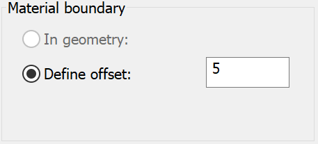
- In the Material boundary section, enter the appropriate offset value in the Define offset text field. To accurately define the offset, you have to consider the size of the tool in addition to the starting stock.
As defined by the offset value, the iMachining technology automatically generates the remaining chain entities to complete the Geometry definition. Clicking Preview enables you to verify that the auto-generated chain entities are correct.
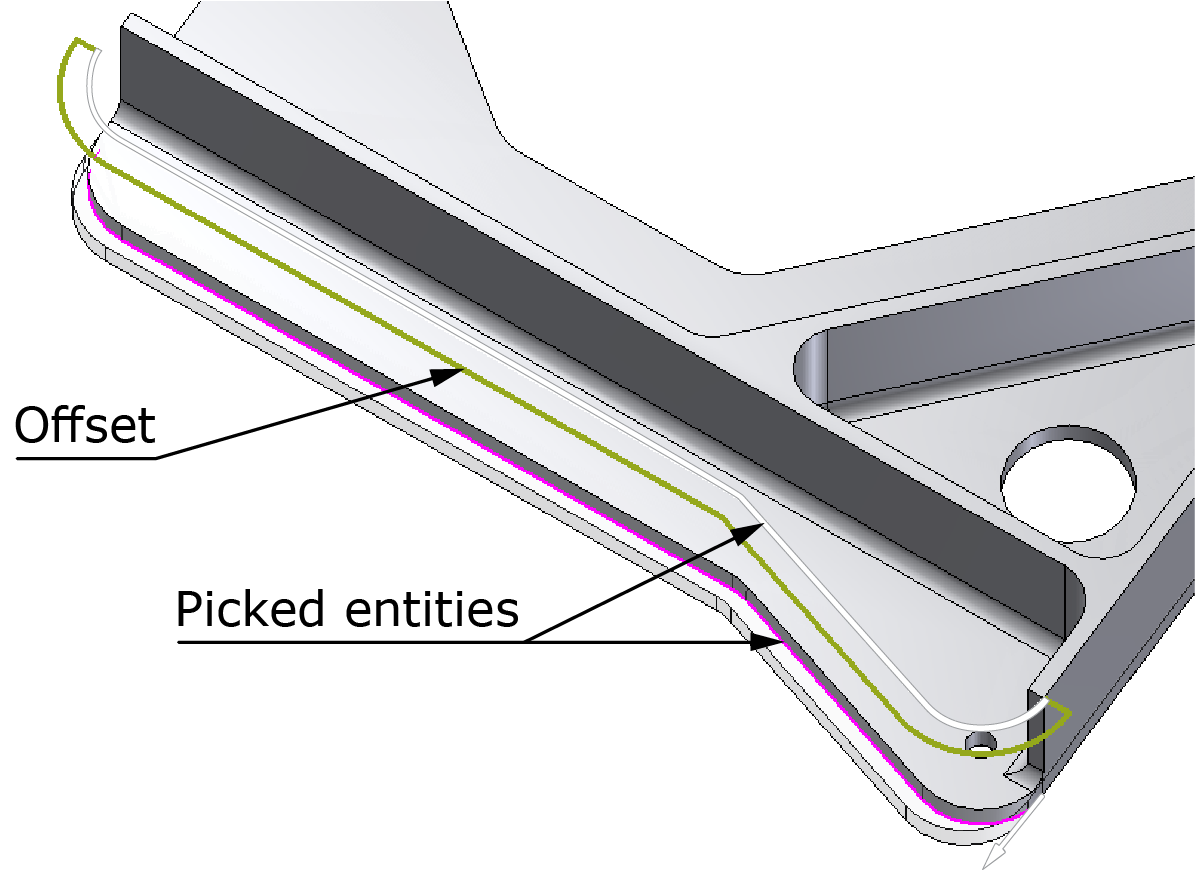
The chain entities projected in white represent the picked entities, while those projected in green represent the auto-generated entities.
Regardless of the geometry type, the auto-generated chains and chain entities are always defined as open, meaning that the tool will approach the material and start machining from those chains.